AT91EB42 Atmel, AT91EB42 Datasheet - Page 8
AT91EB42
Manufacturer Part Number
AT91EB42
Description
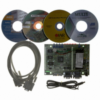
KIT EVAL FOR ARM AT91M42800A
Manufacturer
Atmel
Series
AT91SAM Smart ARMr
Type
MCUr
Datasheet
1.AT91EB42.pdf
(45 pages)
Specifications of AT91EB42
Contents
Evaluation Board, Cable, Power Jack, CD-ROM
For Use With/related Products
AT91M42800A
Lead Free Status / RoHS Status
Contains lead / RoHS non-compliant


1708C–ATARM–12-May-05
Setting Up the AT91EB42 Evaluation Board
2.4
2.5
2.6
2-2
Jumper Settings
Powering Up the
Board
Measuring
Current
Consumption
on the
AT91M42800A
JP1 is used to boot standard or user programs. For standard operations, set it in the
STD position.
JP8 is used to select the core power supply of the AT91M42800A. Operations at 2V are
not supported on the current silicon.
For more information about jumpers and other straps, see Section 5.
DC power is supplied to the board via the 2.1 mm socket (J1) shown in Figure 2-2. The
polarity of the power supply is not critical. The minimum voltage required is 7V.
A battery is supplied on the AT91EB42. It supplies all on-board devices in the same way
that the external DC power operates. A battery fast-charge controller is provided on-
board with a fast-charge indicator (D28), as shown in Figure 2-1.
Figure 2-2. 2.1 mm Socket
The board has a voltage regulator providing +3.3V. The regulator allows the input volt-
age to range from 7V to 12V. When you switch the power on, the red LED marked
POWER lights up. If it does not, switch off and check the power supply connections.
The board is designed to generate the power for the AT91 product, and only the AT91
product, through the jumpers JP5 (V
surements of the consumption of the AT91 product to be made.
See Section 5 for further details.
positive (+)
or
negative (-)
2.1 mm Connector
DDIO
) and JP8 (V
AT91EB42 Evaluation Board User Guide
DDCORE
). This feature enables mea-
Related parts for AT91EB42
Image
Part Number
Description
Manufacturer
Datasheet
Request
R

Part Number:
Description:
DEV KIT FOR AVR/AVR32
Manufacturer:
Atmel
Datasheet:

Part Number:
Description:
INTERVAL AND WIPE/WASH WIPER CONTROL IC WITH DELAY
Manufacturer:
ATMEL Corporation
Datasheet:
Part Number:
Description:
Low-Voltage Voice-Switched IC for Hands-Free Operation
Manufacturer:
ATMEL Corporation
Datasheet:
Part Number:
Description:
MONOLITHIC INTEGRATED FEATUREPHONE CIRCUIT
Manufacturer:
ATMEL Corporation
Datasheet:
Part Number:
Description:
AM-FM Receiver IC U4255BM-M
Manufacturer:
ATMEL Corporation
Datasheet:
Part Number:
Description:
Monolithic Integrated Feature Phone Circuit
Manufacturer:
ATMEL Corporation
Datasheet:
Part Number:
Description:
Multistandard Video-IF and Quasi Parallel Sound Processing
Manufacturer:
ATMEL Corporation
Datasheet:
Part Number:
Description:
High-performance EE PLD
Manufacturer:
ATMEL Corporation
Datasheet:
Part Number:
Description:
8-bit Flash Microcontroller
Manufacturer:
ATMEL Corporation
Datasheet:
Part Number:
Description:
2-Wire Serial EEPROM
Manufacturer:
ATMEL Corporation
Datasheet: