AT91EB42 Atmel, AT91EB42 Datasheet - Page 21
AT91EB42
Manufacturer Part Number
AT91EB42
Description
KIT EVAL FOR ARM AT91M42800A
Manufacturer
Atmel
Series
AT91SAM Smart ARMr
Type
MCUr
Datasheet
1.AT91EB42.pdf
(45 pages)
Specifications of AT91EB42
Contents
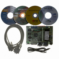
Evaluation Board, Cable, Power Jack, CD-ROM
For Use With/related Products
AT91M42800A
Lead Free Status / RoHS Status
Contains lead / RoHS non-compliant


AT91EB42 Evaluation Board User Guide
Note:
Note:
Note:
Note:
Note:
CB4
Closed
Open
CB5
Closed
Open
CB6
Closed
Open
CB7
Closed
Open
CB8
Closed
Open
(1)
(1)
(1)
(1)
(1)
1. Hardwired default position: To cancel this default configuration, the user should cut
1. Hardwired default position: To cancel this default configuration, the user should cut
1. Hardwired default position: To cancel this default configuration, the user should cut
1. Hardwired default position: To cancel this default configuration, the user should cut
1. Hardwired default position: To cancel this default configuration, the user should cut
the wire on the board.
the wire on the board.
the wire on the board.
the wire on the board.
the wire on the board.
ADC Chip Select Line
ADC (U20) control lines enabled.
ADC (U20) control lines disabled. This authorizes users to connect the
corresponding chip select line to their own resources via the I/O expansion
connector.
Standard Power Supply Supervisory Enabling
Standard power supply is supervised by the ADC (U20) channel 1 via a
resistor bridge. The ratio is set to 0.1013 so that the standard power supply
can be supervised up to 15V.
Standard power supply is not connected to the ADC (U20) channel 1. This
allows the user to connect the corresponding ADC channel to their own
resources via the I/O expansion connector.
VDDCORE Voltage Monitoring
The ADC channel 3 is connected at the V
the user to tune the frequency clock according to the core voltage.
The ADC channel 3 is not connected and it is available on the I/O expansion
connector for user application.
Battery Power Supply Supervisory Enabling
Battery power supply is supervised by the ADC (U20) channel 2 via a
resistor bridge. The ratio is set to 0.24 so that the battery voltage range can
be supervised (5.5V to 6.2V).
Battery power supply is not connected to the ADC (U20) channel 2. This
authorizes the user to connect the corresponding ADC channel to their own
resources via the I/O expansion connector.
Ambient Temperature Monitoring
The ADC channel 0 is connected to a temperature sensor near the
32.768 kHz crystal. This allows the user to evaluate the frequency drift
according to the ambient temperature.
The ADC channel 0 is not connected and it is available on the I/O expansion
connector for the user application.
Appendix A – Configuration Straps
DDCORE
power supply. This allows
1708C–ATARM–12-May-05
5-3
Related parts for AT91EB42
Image
Part Number
Description
Manufacturer
Datasheet
Request
R

Part Number:
Description:
DEV KIT FOR AVR/AVR32
Manufacturer:
Atmel
Datasheet:

Part Number:
Description:
INTERVAL AND WIPE/WASH WIPER CONTROL IC WITH DELAY
Manufacturer:
ATMEL Corporation
Datasheet:
Part Number:
Description:
Low-Voltage Voice-Switched IC for Hands-Free Operation
Manufacturer:
ATMEL Corporation
Datasheet:
Part Number:
Description:
MONOLITHIC INTEGRATED FEATUREPHONE CIRCUIT
Manufacturer:
ATMEL Corporation
Datasheet:
Part Number:
Description:
AM-FM Receiver IC U4255BM-M
Manufacturer:
ATMEL Corporation
Datasheet:
Part Number:
Description:
Monolithic Integrated Feature Phone Circuit
Manufacturer:
ATMEL Corporation
Datasheet:
Part Number:
Description:
Multistandard Video-IF and Quasi Parallel Sound Processing
Manufacturer:
ATMEL Corporation
Datasheet:
Part Number:
Description:
High-performance EE PLD
Manufacturer:
ATMEL Corporation
Datasheet:
Part Number:
Description:
8-bit Flash Microcontroller
Manufacturer:
ATMEL Corporation
Datasheet:
Part Number:
Description:
2-Wire Serial EEPROM
Manufacturer:
ATMEL Corporation
Datasheet: