AT91EB42 Atmel, AT91EB42 Datasheet - Page 16
AT91EB42
Manufacturer Part Number
AT91EB42
Description
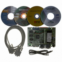
KIT EVAL FOR ARM AT91M42800A
Manufacturer
Atmel
Series
AT91SAM Smart ARMr
Type
MCUr
Datasheet
1.AT91EB42.pdf
(45 pages)
Specifications of AT91EB42
Contents
Evaluation Board, Cable, Power Jack, CD-ROM
For Use With/related Products
AT91M42800A
Lead Free Status / RoHS Status
Contains lead / RoHS non-compliant


1708C–ATARM–12-May-05
Circuit Description
4.3
4.4
4.5
4-2
Memories
Analog-to-digital
Converter
Power and
Crystal Quartz
The schematic (see Figure 6-3 on page 6-4 in Section 6, “Appendix B – Schematics”)
shows one AT49BV162A 2M bytes 16-bit Flash, one AT45DB321 4M bytes serial
DataFlash, one AT24C512 64K bytes EEPROM, one AT25256 32K Bytes EEPROM
and two 128K/512K x 8 SRAM devices.
Note:
An on-board 4-channel, 10-bit ADC device (TLV1504 by Texas Instruments) is featured
on the AT91EB42. This device is interfaced to the AT91M42800A via the SPIA periph-
eral and embeds its voltage reference equal to 2V. Four channels are used on the
AT91EB42 for the following measurements:
! Channel 0 is used to measure the temperature near the 32.768 kHz crystal.
! Channel 1 is dedicated to supervise the External Power Supply.
! Channel 2 is dedicated to supervise the Battery Power Supply.
! Channel 3 is dedicated to supervise the V
Each ADC channel is fitted on the I/O extension connector and can be used in other
applications. For this reason, each ADC input can be taken away from its function by its
appropriate jumper.
The AT91M42800A master clock is derived from a 32.768 kHz crystal. The on-chip low-
power oscillator together with two PLL-based frequency multipliers and the prescaler
results in a programmable master clock between 500 Hz and 33 MHz. A temperature
sensor has been placed near the 32.768 kHz crystal and the analog signal output has
been fitted to Channel 0 of the on-board ADC.
Two sets of components for the PLL filters are fitted by default on the board (see Figure
6-6 on page 6-7 in Section 6, “Appendix B – Schematics”). They are calculated to pro-
vide a 16.77 MHz (PLLA: multiplier factor of 512 and settling time of 600 µs) or a 32.768
MHz (PLLB: multiplier factor of 1000 and settling time of 6 ms) master clock frequency.
For further details, see the application note “Crystal Oscillator and PLL Considerations
for AT91M42800A and AT91M55800A”, literature number 1740A. A PLL Filter Calcula-
tor Tool is also available. See “Automatic_calculation_xls.zip”.
The voltage regulator provides 3.3V to the board and will light the red POWER LED
(D11) when operating.
Power can be applied via the 2.1 mm connector to the regulator in either polarity
because of the diode-rectifying circuit. Another regulator allows the user to power the
AT91M42800A core with 3.3V or 1.8V by means of the JP8 jumper.
All functions can be supplied by the on-board battery. A connector permits the user to
disconnect the battery. The type of battery and connection to be used are shown in Sec-
tion 6 of this user guide. This type of battery will ensure the power supply of the board
for approximately one hour. A battery fast-charge controller is provided on-board to
charge it and maintains the full charge. The user is warned while the fast-charge is
started via the on-board indicator (D28) or a logical signal on I/O port PB18.
The AT24C512 64K byte EEPROM and the AT25256 32K byte EEPROM are
not mounted.
DDCORE
AT91EB42 Evaluation Board User Guide
.
Related parts for AT91EB42
Image
Part Number
Description
Manufacturer
Datasheet
Request
R

Part Number:
Description:
DEV KIT FOR AVR/AVR32
Manufacturer:
Atmel
Datasheet:

Part Number:
Description:
INTERVAL AND WIPE/WASH WIPER CONTROL IC WITH DELAY
Manufacturer:
ATMEL Corporation
Datasheet:
Part Number:
Description:
Low-Voltage Voice-Switched IC for Hands-Free Operation
Manufacturer:
ATMEL Corporation
Datasheet:
Part Number:
Description:
MONOLITHIC INTEGRATED FEATUREPHONE CIRCUIT
Manufacturer:
ATMEL Corporation
Datasheet:
Part Number:
Description:
AM-FM Receiver IC U4255BM-M
Manufacturer:
ATMEL Corporation
Datasheet:
Part Number:
Description:
Monolithic Integrated Feature Phone Circuit
Manufacturer:
ATMEL Corporation
Datasheet:
Part Number:
Description:
Multistandard Video-IF and Quasi Parallel Sound Processing
Manufacturer:
ATMEL Corporation
Datasheet:
Part Number:
Description:
High-performance EE PLD
Manufacturer:
ATMEL Corporation
Datasheet:
Part Number:
Description:
8-bit Flash Microcontroller
Manufacturer:
ATMEL Corporation
Datasheet:
Part Number:
Description:
2-Wire Serial EEPROM
Manufacturer:
ATMEL Corporation
Datasheet: