C8051F411EK Silicon Laboratories Inc, C8051F411EK Datasheet - Page 73
C8051F411EK
Manufacturer Part Number
C8051F411EK
Description
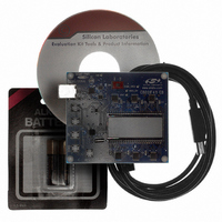
KIT EVAL FOR C8051F411
Manufacturer
Silicon Laboratories Inc
Type
MCUr
Specifications of C8051F411EK
Contents
Evaluation Board, CD-ROM, USB Cable, Batteries and User Guide
Processor To Be Evaluated
C8051F41x
Interface Type
USB
Silicon Manufacturer
Silicon Labs
Core Architecture
8051
Silicon Core Number
C8051F411
Silicon Family Name
C8051F41x
Kit Contents
LCD Based Evaluation Board, USB Cable, Software CD And Quick-Start Guide
Lead Free Status / RoHS Status
Contains lead / RoHS non-compliant
For Use With/related Products
Silicon Laboratories C8051F41x
For Use With
336-1315 - KIT REF DESIGN VOICE RECORD F41X
Lead Free Status / Rohs Status
Lead free / RoHS Compliant
Other names
336-1317


6.3.
The IDA0 output is connected to P0.0, and the IDA1 output can be connected to P0.0 or P0.1. The output
pin for IDA1 is selected using IDAMRG (REF0CN.7). When the enable bits for both IDACs (IDAnEN) are
set to ‘0’, the IDAC outputs behave as a normal GPIO pins. When either IDAC’s enable bit is set to ‘1’, the
digital output drivers and weak pullup for the selected IDAC pin are automatically disabled, and the pin is
connected to the IDAC output. When using the IDACs, the selected IDAC pin(s) should be skipped in the
Crossbar by setting the corresponding PnSKIP bits to a ‘1’. Figure 6.3 shows the pin connections for IDA0
and IDA1.
When both IDACs are enabled and IDAMRG is set to logic 1, the output of both IDACs is merged onto
P0.0.
Bits 7–0: IDA1 Data Word High-Order Bits.
Bits 7–0: IDA1 Data Word Low-Order Bits.
R/W
R/W
Bit7
Bit7
IDAC External Pin Connections
For IDA0RJST = 0:
Bits 7-0 hold the most significant 8-bits of the 12-bit IDA1 Data Word.
For IDA0RJST = 1:
Bits 3-0 hold the most significant 4-bits of the 12-bit IDA1 Data Word. Bits 7–4 are 0000b.
For IDA0RJST = 0:
Bits 7-4 hold the least significant 4-bits of the 12-bit IDA1 Data Word. Bits 3–0 are 0000b.
For IDA0RJST = 1:
Bits 7–0 hold the least significant 8-bits of the 12-bit IDA1 Data Word.
R/W
R/W
Bit6
Bit6
SFR Definition 6.5. IDA1H: IDA0 Data High Byte
SFR Definition 6.6. IDA1L: IDA1 Data Low Byte
R/W
R/W
Bit5
Bit5
R/W
R/W
Bit4
Bit4
Rev. 1.1
R/W
R/W
Bit3
Bit3
R/W
R/W
Bit2
Bit2
C8051F410/1/2/3
R/W
R/W
Bit1
Bit1
SFR Address:
SFR Address:
R/W
R/W
Bit0
Bit0
0xF5
0xF4
00000000
00000000
Reset Value
Reset Value
73
Related parts for C8051F411EK
Image
Part Number
Description
Manufacturer
Datasheet
Request
R

Part Number:
Description:
SMD/C°/SINGLE-ENDED OUTPUT SILICON OSCILLATOR
Manufacturer:
Silicon Laboratories Inc
Part Number:
Description:
Manufacturer:
Silicon Laboratories Inc
Datasheet:
Part Number:
Description:
N/A N/A/SI4010 AES KEYFOB DEMO WITH LCD RX
Manufacturer:
Silicon Laboratories Inc
Datasheet:
Part Number:
Description:
N/A N/A/SI4010 SIMPLIFIED KEY FOB DEMO WITH LED RX
Manufacturer:
Silicon Laboratories Inc
Datasheet:
Part Number:
Description:
N/A/-40 TO 85 OC/EZLINK MODULE; F930/4432 HIGH BAND (REV E/B1)
Manufacturer:
Silicon Laboratories Inc
Part Number:
Description:
EZLink Module; F930/4432 Low Band (rev e/B1)
Manufacturer:
Silicon Laboratories Inc
Part Number:
Description:
I°/4460 10 DBM RADIO TEST CARD 434 MHZ
Manufacturer:
Silicon Laboratories Inc
Part Number:
Description:
I°/4461 14 DBM RADIO TEST CARD 868 MHZ
Manufacturer:
Silicon Laboratories Inc
Part Number:
Description:
I°/4463 20 DBM RFSWITCH RADIO TEST CARD 460 MHZ
Manufacturer:
Silicon Laboratories Inc
Part Number:
Description:
I°/4463 20 DBM RADIO TEST CARD 868 MHZ
Manufacturer:
Silicon Laboratories Inc
Part Number:
Description:
I°/4463 27 DBM RADIO TEST CARD 868 MHZ
Manufacturer:
Silicon Laboratories Inc
Part Number:
Description:
I°/4463 SKYWORKS 30 DBM RADIO TEST CARD 915 MHZ
Manufacturer:
Silicon Laboratories Inc
Part Number:
Description:
N/A N/A/-40 TO 85 OC/4463 RFMD 30 DBM RADIO TEST CARD 915 MHZ
Manufacturer:
Silicon Laboratories Inc
Part Number:
Description:
I°/4463 20 DBM RADIO TEST CARD 169 MHZ
Manufacturer:
Silicon Laboratories Inc