MC56F8006DEMO Freescale Semiconductor, MC56F8006DEMO Datasheet - Page 40
MC56F8006DEMO
Manufacturer Part Number
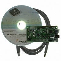
MC56F8006DEMO
Description
DEMO BOARD FOR MC56F8006
Manufacturer
Freescale Semiconductor
Type
DSPr
Datasheets
1.MC56F8006DEMO.pdf
(13 pages)
2.MC56F8006DEMO.pdf
(8 pages)
3.MC56F8006DEMO.pdf
(2 pages)
4.MC56F8006DEMO.pdf
(100 pages)
Specifications of MC56F8006DEMO
Contents
Board
Processor To Be Evaluated
MC56F8006
Interface Type
RS-232, USB
Operating Supply Voltage
3.3 V
Silicon Manufacturer
Freescale
Core Architecture
56800/E
Core Sub-architecture
56800/E
Silicon Core Number
MC56F
Silicon Family Name
MC56F80xx
Rohs Compliant
Yes
For Use With/related Products
MC56F8006
Lead Free Status / RoHS Status
Lead free / RoHS Compliant


Specifications
7.2.4
7.2.4.1
A user can un-secure a secured device by programming the word 0x0000 into program flash location 0x00 1FF7. After
completing the programming, the JTAG TAP controller and the device must be reset to return to normal unsecured operation.
You are responsible for directing the device to invoke the flash programming subroutine to reprogram the word 0x0000 into
program flash location 0x00 1FF7. This is done by, for example, toggling a specific pin or downloading a user-defined key
through serial interfaces.
7.2.4.2
It is possible to temporarily bypass the security through a back door access scheme, using a 4-word key, to temporarily unlock
of the flash. A back door access requires support from the embedded software. This software would typically permit an external
user to enter a four word code through one of the communications interfaces and then use it to attempt the unlock sequence. If
your input matches the four word code stored at location 0x00 1FFC–0x00 1FFF in the flash memory, the part immediately
becomes unsecured (at runtime) and you can access internal memory via JTAG/EOnCE port. Refer to the MC56F8006
Peripheral Reference Manual for detail. The key must be entered in four consecutive accesses to the flash, so this routine should
be designed to run in RAM.
7.3
The recommended method of unsecuring a secured device for product analysis of field failures is via the method described in
Section 7.2.4.2, “Presenting Back Door Access Key to the Flash
with the details of the protocol to access the subroutines in flash memory. An alternative method for performing analysis on a
secured device would be to mass-erase and reprogram the flash with the original code, but modify the security word or not
program the security word.
8
8.1
The 56F8006/56F8002 is fabricated in high-density low power and low leakage CMOS with a maximum voltage of 3.6 V digital
inputs during normal operation without causing damage.
Absolute maximum ratings in
beyond these ratings may affect device reliability or cause permanent damage to the device.
Unless otherwise stated, all specifications within this chapter apply over the temperature range of –40ºC to 105ºC ambient
temperature over the following supply ranges: V
40
Product Analysis
Specifications
General Characteristics
Flash Lockout Recovery without Mass Erase
Without Presenting Back Door Access Keys to the Flash Unit
Presenting Back Door Access Key to the Flash Unit
This device contains protective circuitry to guard against damage due to high static voltage
or electrical fields. However, normal precautions are advised to avoid application of any
voltages higher than maximum-rated voltages to this high-impedance circuit. Reliability of
operation is enhanced if unused inputs are tied to an appropriate voltage level.
Table 12
MC56F8006/MC56F8002 Digital Signal Controller, Rev. 3
Flash contents can be programmed only from 1s to 0s.
are stress ratings only, and functional operation at the maximum is not guaranteed. Stress
SS
= V
SSA
CAUTION
NOTE
= 0V, V
Unit.” The customer would need to supply technical support
DD
= V
DDA
= 3.0–3.6 V, CL < 50 pF, f
Freescale Semiconductor
OP
= 32 MHz
Related parts for MC56F8006DEMO
Image
Part Number
Description
Manufacturer
Datasheet
Request
R

Part Number:
Description:
Manufacturer:
Freescale Semiconductor, Inc
Datasheet:
Part Number:
Description:
Manufacturer:
Freescale Semiconductor, Inc
Datasheet:
Part Number:
Description:
Manufacturer:
Freescale Semiconductor, Inc
Datasheet:
Part Number:
Description:
Manufacturer:
Freescale Semiconductor, Inc
Datasheet:
Part Number:
Description:
Manufacturer:
Freescale Semiconductor, Inc
Datasheet:
Part Number:
Description:
Manufacturer:
Freescale Semiconductor, Inc
Datasheet:
Part Number:
Description:
Manufacturer:
Freescale Semiconductor, Inc
Datasheet:
Part Number:
Description:
Manufacturer:
Freescale Semiconductor, Inc
Datasheet:
Part Number:
Description:
Manufacturer:
Freescale Semiconductor, Inc
Datasheet:
Part Number:
Description:
Manufacturer:
Freescale Semiconductor, Inc
Datasheet:
Part Number:
Description:
Manufacturer:
Freescale Semiconductor, Inc
Datasheet:
Part Number:
Description:
Manufacturer:
Freescale Semiconductor, Inc
Datasheet:
Part Number:
Description:
Manufacturer:
Freescale Semiconductor, Inc
Datasheet:
Part Number:
Description:
Manufacturer:
Freescale Semiconductor, Inc
Datasheet:
Part Number:
Description:
Manufacturer:
Freescale Semiconductor, Inc
Datasheet: