MC56F8006DEMO Freescale Semiconductor, MC56F8006DEMO Datasheet - Page 42
MC56F8006DEMO
Manufacturer Part Number
MC56F8006DEMO
Description
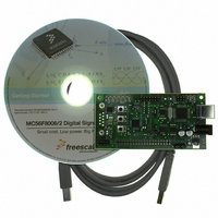
DEMO BOARD FOR MC56F8006
Manufacturer
Freescale Semiconductor
Type
DSPr
Datasheets
1.MC56F8006DEMO.pdf
(13 pages)
2.MC56F8006DEMO.pdf
(8 pages)
3.MC56F8006DEMO.pdf
(2 pages)
4.MC56F8006DEMO.pdf
(100 pages)
Specifications of MC56F8006DEMO
Contents
Board
Processor To Be Evaluated
MC56F8006
Interface Type
RS-232, USB
Operating Supply Voltage
3.3 V
Silicon Manufacturer
Freescale
Core Architecture
56800/E
Core Sub-architecture
56800/E
Silicon Core Number
MC56F
Silicon Family Name
MC56F80xx
Rohs Compliant
Yes
For Use With/related Products
MC56F8006
Lead Free Status / RoHS Status
Lead free / RoHS Compliant


Specifications
A device is defined as a failure if after exposure to ESD pulses the device no longer meets the device specification. Complete
DC parametric and functional testing is performed per the applicable device specification at room temperature followed by hot
temperature, unless specified otherwise in the device specification.
8.3
This section provides information about operating temperature range, power dissipation, and package thermal resistance. Power
dissipation on I/O pins is usually small compared to the power dissipation in on-chip logic and voltage regulator circuits, and
it is user-determined rather than being controlled by the MCU design. To take P
the difference between actual pin voltage and V
unusually high pin current (heavy loads), the difference between pin voltage and V
42
Thermal Characteristics
1
Parameter is achieved by design characterization on a small sample size from typical devices un-
der typical conditions unless otherwise noted.
ESD for Charge Device Model (CDM)
ESD for Human Body Model (HBM)
Latch-up current at T
Latch-up
Machine
ESD for Machine Model (MM)
Human
Junction to ambient
Junction to ambient
Junction to ambient
Model
Natural convection
Natural convection
Body
Characteristic
(@200 ft/min)
Characteristic
Table 15. 28SOIC Package Thermal Characteristics
MC56F8006/MC56F8002 Digital Signal Controller, Rev. 3
Maximum Input Voltage Limit
Minimum inpUt Voltage Limit
Number of Pulses per Pin
Number of Pulses per Pin
Table 13. ESD and Latch-up Test Conditions
A
Storage Capacitance
Storage Capacitance
Table 14. 56F8006/56F8002 ESD Protection
= 85
Series Resistance
Series Resistance
1
Description
o
C (I
LAT
SS
Single layer board
Single layer board
Four layer board
or V
)
Comments
(2s2p)
DD
(1s)
(1s)
and multiply by the pin current for each I/O pin. Except in cases of
2000
Min
200
750
100
Symbol
R1
R1
—
—
C
C
Symbol
R
R
R
Typ
JMA
JMA
—
—
—
JA
I/O
into account in power calculations, determine
SS
or V
Value
1500
–2.5
100
200
7.5
(LQFP)
3
0
3
Value
Max
DD
—
—
—
70
47
55
will be very small.
Freescale Semiconductor
Unit
pF
pF
V
V
Unit
°C/W
°C/W
°C/W
Unit
mA
V
V
V
Related parts for MC56F8006DEMO
Image
Part Number
Description
Manufacturer
Datasheet
Request
R

Part Number:
Description:
Manufacturer:
Freescale Semiconductor, Inc
Datasheet:
Part Number:
Description:
Manufacturer:
Freescale Semiconductor, Inc
Datasheet:
Part Number:
Description:
Manufacturer:
Freescale Semiconductor, Inc
Datasheet:
Part Number:
Description:
Manufacturer:
Freescale Semiconductor, Inc
Datasheet:
Part Number:
Description:
Manufacturer:
Freescale Semiconductor, Inc
Datasheet:
Part Number:
Description:
Manufacturer:
Freescale Semiconductor, Inc
Datasheet:
Part Number:
Description:
Manufacturer:
Freescale Semiconductor, Inc
Datasheet:
Part Number:
Description:
Manufacturer:
Freescale Semiconductor, Inc
Datasheet:
Part Number:
Description:
Manufacturer:
Freescale Semiconductor, Inc
Datasheet:
Part Number:
Description:
Manufacturer:
Freescale Semiconductor, Inc
Datasheet:
Part Number:
Description:
Manufacturer:
Freescale Semiconductor, Inc
Datasheet:
Part Number:
Description:
Manufacturer:
Freescale Semiconductor, Inc
Datasheet:
Part Number:
Description:
Manufacturer:
Freescale Semiconductor, Inc
Datasheet:
Part Number:
Description:
Manufacturer:
Freescale Semiconductor, Inc
Datasheet:
Part Number:
Description:
Manufacturer:
Freescale Semiconductor, Inc
Datasheet: