MC56F8006DEMO Freescale Semiconductor, MC56F8006DEMO Datasheet - Page 51
MC56F8006DEMO
Manufacturer Part Number
MC56F8006DEMO
Description
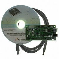
DEMO BOARD FOR MC56F8006
Manufacturer
Freescale Semiconductor
Type
DSPr
Datasheets
1.MC56F8006DEMO.pdf
(13 pages)
2.MC56F8006DEMO.pdf
(8 pages)
3.MC56F8006DEMO.pdf
(2 pages)
4.MC56F8006DEMO.pdf
(100 pages)
Specifications of MC56F8006DEMO
Contents
Board
Processor To Be Evaluated
MC56F8006
Interface Type
RS-232, USB
Operating Supply Voltage
3.3 V
Silicon Manufacturer
Freescale
Core Architecture
56800/E
Core Sub-architecture
56800/E
Silicon Core Number
MC56F
Silicon Family Name
MC56F80xx
Rohs Compliant
Yes
For Use With/related Products
MC56F8006
Lead Free Status / RoHS Status
Lead free / RoHS Compliant


8.8
8.9
Freescale Semiconductor
1
2
3
4
5
Accumulated jitter using an 8 MHz external crystal as the PLL source
An externally supplied reference clock should be as free as possible from any phase jitter for the PLL to work correctly. The
PLL is optimized for 8 MHz input.
The core system clock operates at 1/6 of the PLL output frequency.
This is the time required after the PLL is enabled to ensure reliable operation.
From powerdown to powerup state at 32 MHz system clock state.
This is measured on the CLKO signal (programmed as system clock) over 264 system clocks at 32 MHz system clock
frequency and using an 8 MHz oscillator frequency.
1
2
3
4
5
Input high voltage overdrive by an external clock
Input high voltage overdrive by an external clock
Parameters listed are guaranteed by design.
See
The chip may not function if the high or low pulse width is smaller than 6.25 ns.
External clock input rise time is measured from 10% to 90%.
External clock input fall time is measured from 90% to 10%.
Frequency of operation (external clock driver)
External
Clock
External Clock Operation Timing
Phase Locked Loop Timing
Figure 20
Note: The midpoint is V
External clock input rise time
External clock input fall time
PLL input reference frequency
Clock pulse width
for detail on using the recommended connection of an external clock driver.
Characteristic
10%
50%
90%
PLL output frequency
Cycle-to-cycle jitter
Table 23. External Clock Operation Timing Requirements
PLL lock time
Characteristic
t
PW
MC56F8006/MC56F8002 Digital Signal Controller, Rev. 3
IL
3
+ (V
Table 24. Phase Locked Loop Timing
3 4
Figure 20. External Clock Timing
IH
5
4
– V
2
IL
t
)/2.
1
PW
2
Symbol
f
t
t
t
V
osc
PW
rise
V
fall
ih
il
5
0.85V
6.25
Min
—
—
—
—
Symbol
t
fall
t
jitterpll
DD
t
f
f
J
plls
ref
op
A
Typ
—
—
—
—
—
—
Min
120
—
—
—
4
1
t
rise
0.3V
Typ
192
350
40
Max
—
8
64
—
—
3
3
DD
10%
50%
90%
Max
0.37
100
—
—
—
Specifications
V
V
Unit
MHz
IH
ns
ns
ns
V
V
IL
Unit
MHz
MHz
µs
ps
%
51
Related parts for MC56F8006DEMO
Image
Part Number
Description
Manufacturer
Datasheet
Request
R

Part Number:
Description:
Manufacturer:
Freescale Semiconductor, Inc
Datasheet:
Part Number:
Description:
Manufacturer:
Freescale Semiconductor, Inc
Datasheet:
Part Number:
Description:
Manufacturer:
Freescale Semiconductor, Inc
Datasheet:
Part Number:
Description:
Manufacturer:
Freescale Semiconductor, Inc
Datasheet:
Part Number:
Description:
Manufacturer:
Freescale Semiconductor, Inc
Datasheet:
Part Number:
Description:
Manufacturer:
Freescale Semiconductor, Inc
Datasheet:
Part Number:
Description:
Manufacturer:
Freescale Semiconductor, Inc
Datasheet:
Part Number:
Description:
Manufacturer:
Freescale Semiconductor, Inc
Datasheet:
Part Number:
Description:
Manufacturer:
Freescale Semiconductor, Inc
Datasheet:
Part Number:
Description:
Manufacturer:
Freescale Semiconductor, Inc
Datasheet:
Part Number:
Description:
Manufacturer:
Freescale Semiconductor, Inc
Datasheet:
Part Number:
Description:
Manufacturer:
Freescale Semiconductor, Inc
Datasheet:
Part Number:
Description:
Manufacturer:
Freescale Semiconductor, Inc
Datasheet:
Part Number:
Description:
Manufacturer:
Freescale Semiconductor, Inc
Datasheet:
Part Number:
Description:
Manufacturer:
Freescale Semiconductor, Inc
Datasheet: