MC56F8006DEMO Freescale Semiconductor, MC56F8006DEMO Datasheet - Page 78
MC56F8006DEMO
Manufacturer Part Number
MC56F8006DEMO
Description
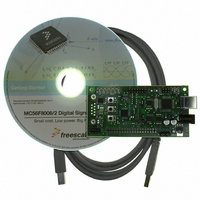
DEMO BOARD FOR MC56F8006
Manufacturer
Freescale Semiconductor
Type
DSPr
Datasheets
1.MC56F8006DEMO.pdf
(13 pages)
2.MC56F8006DEMO.pdf
(8 pages)
3.MC56F8006DEMO.pdf
(2 pages)
4.MC56F8006DEMO.pdf
(100 pages)
Specifications of MC56F8006DEMO
Contents
Board
Processor To Be Evaluated
MC56F8006
Interface Type
RS-232, USB
Operating Supply Voltage
3.3 V
Silicon Manufacturer
Freescale
Core Architecture
56800/E
Core Sub-architecture
56800/E
Silicon Core Number
MC56F
Silicon Family Name
MC56F80xx
Rohs Compliant
Yes
For Use With/related Products
MC56F8006
Lead Free Status / RoHS Status
Lead free / RoHS Compliant


Interrupt Vector Table
Appendix A
Interrupt Vector Table
Table 41
organized with higher-priority vectors at the top and lower-priority interrupts lower in the table. As indicated, the priority of an
interrupt can be assigned to different levels, allowing some control over interrupt priorities. All level 3 interrupts are serviced
before level 2 and so on. For a selected priority level, the lowest vector number has the highest priority.
The location of the vector table is determined by the vector base address (VBA). Please see the MC56F8006 Peripheral
Reference Manual for detail.
By default, the chip reset address and COP reset address correspond to vector 0 and 1 of the interrupt vector table. In these
instances, the first two locations in the vector table must contain branch or JMP instructions. All other entries must contain JSR
instructions.
78
Introduction
Section 6.7, “PWM, PDB, PGA, and ADC
Connections,”
Table 12 on page 41
Table 20 on page 45
Table 21 on page 49
Table 25
Table 30 on page 59
Appendix
Table 42 on page 80
Peripheral
Core
Core
Core
Core
Core
Core
Core
Core
Core
Core
provides the 56F8006/56F8002’s reset and interrupt priority structure, including on-chip peripherals. The table is
and
B on page 80
on page 1
Figure 21 on page 52
on page 37
Number
Vector
Location
2
3
4
5
6
7
9
9
Encoding
User
N/A
N/A
N/A
N/A
N/A
N/A
N/A
N/A
MC56F8006/MC56F8002 Digital Signal Controller, Rev. 3
Table 40. Changes Between Revisions 2 and 3
Table 41. Interrupt Vector Table Contents
Priority
Level
Added part marking for devices covered by this document
Updated routing details for ANB24 and ANB25
Removed row about open drain mode (GPIO supports only push-pull mode)
Updated specifications for low-voltage detection threshold (high and low range) and
low-voltage warning threshold
Updated all Supply Current Consumption specifications
Updated ROSC variation over temperature specifications (both ranges)
Removed I
is empty (fast mode and FIFO not supported)
Added note explaining ADC and GPIO naming conventions
For I2C_SMB_CSR, clarified that bits 7 and 6 are reserved
3
3
3
3
3
3
3
3
Vector Base
Address +
2
P:0x0C
C fast mode specifications and footnote about setup time if the TX FIFO
P:0x00
P:0x02
P:0x04
P:0x06
P:0x08
P:0x0A
P:0x0E
P:0x10
P:0x12
Description
Reserved for COP Reset Overlay
EOnCE Transmit Register Empty
Misaligned Long Word Access
EOnCE Receive Register Full
Reserved for Reset Overlay
EOnCE Breakpoint Unit
EOnCE Step Counter
EOnCE Trace Buffer
1
Interrupt Function
HW Stack Overflow
Illegal Instruction
Freescale Semiconductor
2
Related parts for MC56F8006DEMO
Image
Part Number
Description
Manufacturer
Datasheet
Request
R

Part Number:
Description:
Manufacturer:
Freescale Semiconductor, Inc
Datasheet:
Part Number:
Description:
Manufacturer:
Freescale Semiconductor, Inc
Datasheet:
Part Number:
Description:
Manufacturer:
Freescale Semiconductor, Inc
Datasheet:
Part Number:
Description:
Manufacturer:
Freescale Semiconductor, Inc
Datasheet:
Part Number:
Description:
Manufacturer:
Freescale Semiconductor, Inc
Datasheet:
Part Number:
Description:
Manufacturer:
Freescale Semiconductor, Inc
Datasheet:
Part Number:
Description:
Manufacturer:
Freescale Semiconductor, Inc
Datasheet:
Part Number:
Description:
Manufacturer:
Freescale Semiconductor, Inc
Datasheet:
Part Number:
Description:
Manufacturer:
Freescale Semiconductor, Inc
Datasheet:
Part Number:
Description:
Manufacturer:
Freescale Semiconductor, Inc
Datasheet:
Part Number:
Description:
Manufacturer:
Freescale Semiconductor, Inc
Datasheet:
Part Number:
Description:
Manufacturer:
Freescale Semiconductor, Inc
Datasheet:
Part Number:
Description:
Manufacturer:
Freescale Semiconductor, Inc
Datasheet:
Part Number:
Description:
Manufacturer:
Freescale Semiconductor, Inc
Datasheet:
Part Number:
Description:
Manufacturer:
Freescale Semiconductor, Inc
Datasheet: