DK-VIDEO-4SGX230N Altera, DK-VIDEO-4SGX230N Datasheet - Page 17
DK-VIDEO-4SGX230N
Manufacturer Part Number
DK-VIDEO-4SGX230N
Description
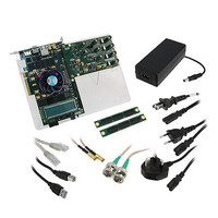
VIDEO KIT STRATIX IV EP4SGX230
Manufacturer
Altera
Series
Stratix® IVr
Type
FPGAr
Datasheet
1.DK-VIDEO-4SGX230N.pdf
(58 pages)
Specifications of DK-VIDEO-4SGX230N
Contents
Board, Daughter Card, Cables, CD, DVD, Power Supply
Silicon Manufacturer
Altera
Core Architecture
FPGA
Core Sub-architecture
Stratix
Silicon Core Number
EP4S
Silicon Family Name
Stratix IV GX
Rohs Compliant
Yes
For Use With/related Products
EP4SGX230K
Lead Free Status / RoHS Status
Lead free / RoHS Compliant
Other names
544-2602


Introduction
Setting Up the Board
© November 2009 Altera Corporation
The instructions in this chapter explain how to set up the Stratix IV GX FPGA
development board.
To set up and power up the board, perform the following steps:
1. The Stratix IV GX FPGA development board ships with its board switches
2. The development board ships with example designs stored in the flash memory
3. Connect the SDI HSMC to the host board by performing the following steps:
4. Connect the DC adapter (+16 V, 3.75 A) to the DC power jack (J4) on the FPGA
5. Set the POWER switch (SW1) to the on position. When power is supplied to the
preconfigured to support the example designs in the development kit. If you
suspect your board might not be currently configured with the default settings,
follow the instructions in
the board to its factory settings before proceeding.
device. Verify the rotary switch (SW2) is set to the 0 position to load the design
stored in the factory portion of flash memory.
location on the Stratix IV GX FPGA development board.
a. Attach two standoffs at the corners of the SDI HSMC opposite the HSMC
b. Connect the J19 connector on the SDI HSMC to the J1 connector on the host
c. For added stability, optionally screw the two boards together using standoffs
d. Connect two SMA cables of equal length from J17 and J18 on the SDI HSMC to
f
board and plug the cord into a power outlet.
c
board, a blue LED (D24) illuminates indicating that the board has power.
connector. Place the standoffs under the board and hand-fasten screws from
the top through the holes adjacent to the AES audio BNC connectors J15 and J3.
board. The host connector is labeled HSMC Port A and is the left connector on
the host board.
and the mounting holes common to both boards.
J14 and J15 on the host board. This connection supplies the SDI HSMC
reference clock to the host board.
Use only the supplied power supply. Power regulation circuitry on the
board can be damaged by power supplies with greater voltage.
For information about the SDI HSMC, refer to the
Manual.
“Factory Default Switch Settings” on page 4–2
4. Development Board Setup
Audio Video Development Kit, Stratix IV GX Edition User Guide
Figure 4–1
shows the rotary switch
SDI HSMC Reference
to return
Related parts for DK-VIDEO-4SGX230N
Image
Part Number
Description
Manufacturer
Datasheet
Request
R


Part Number:
Description:
VIDEO KIT W/CYCLONE II EP2C70N
Manufacturer:
Altera
Datasheet:

Part Number:
Description:
CYCLONE II STARTER KIT EP2C20N
Manufacturer:
Altera
Datasheet:


Part Number:
Description:
CPLD, EP610 Family, ECMOS Process, 300 Gates, 16 Macro Cells, 16 Reg., 16 User I/Os, 5V Supply, 35 Speed Grade, 24DIP
Manufacturer:
Altera Corporation
Datasheet:
Part Number:
Description:
CPLD, EP610 Family, ECMOS Process, 300 Gates, 16 Macro Cells, 16 Reg., 16 User I/Os, 5V Supply, 15 Speed Grade, 24DIP
Manufacturer:
Altera Corporation
Datasheet:
Part Number:
Description:
Manufacturer:
Altera Corporation
Datasheet:
Part Number:
Description:
CPLD, EP610 Family, ECMOS Process, 300 Gates, 16 Macro Cells, 16 Reg., 16 User I/Os, 5V Supply, 30 Speed Grade, 24DIP
Manufacturer:
Altera Corporation
Datasheet:
Part Number:
Description:
High-performance, low-power erasable programmable logic devices with 8 macrocells, 10ns
Manufacturer:
Altera Corporation
Datasheet:
Part Number:
Description:
High-performance, low-power erasable programmable logic devices with 8 macrocells, 7ns
Manufacturer:
Altera Corporation
Datasheet:
Part Number:
Description:
Classic EPLD
Manufacturer:
Altera Corporation
Datasheet:
Part Number:
Description:
High-performance, low-power erasable programmable logic devices with 8 macrocells, 10ns
Manufacturer:
Altera Corporation
Datasheet:
Part Number:
Description:
Manufacturer:
Altera Corporation
Datasheet:
Part Number:
Description:
Manufacturer:
Altera Corporation
Datasheet: