DM300014 Microchip Technology, DM300014 Datasheet - Page 41
DM300014
Manufacturer Part Number
DM300014
Description
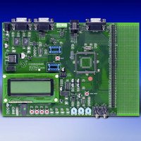
BOARD DEMO DSPICDEM 1.1 GEN PURP
Manufacturer
Microchip Technology
Datasheet
1.DM300014.pdf
(72 pages)
Specifications of DM300014
Processor To Be Evaluated
PIC30F
Data Bus Width
16 bit
Interface Type
RS-485, CAN, SPI
Lead Free Status / RoHS Status
Lead free / RoHS Compliant
Lead Free Status / RoHS Status
Lead free / RoHS Compliant, Lead free / RoHS Compliant


3.5
2003 Microchip Technology Inc.
dsPIC30F DEMONSTRATION PERFORMANCE METRICS
3.4.3.6
Timer1 is a 16-bit timer that uses the instruction cycle as its time-base. It is configured
to time out and generate an interrupt every 125 microseconds. The Timer1 Interrupt
Service Routine (ISR) loads the SPI 2 buffer with a value from a sine table. The SPI 2
module is then used to transmit the sine sample to digital potentiometer MCP41010.
The MCP41010 output is connected to pin AN3/RB3 of the dsPIC30F device.
3.4.3.7
LEDs 1-4 count upward in binary form from 0 through 15. The count rate is controlled
by the 16-bit Timer2 module, which expires every second as it is operated in a 256:1
prescale mode, with the instruction cycle being the count interval.
3.4.3.8
The Timer3 count is configured to expire every 1.14 seconds. In the Timer3 ISR, a
software flag is used to determine whether data needs to be updated to the PC via the
UART2 module. Thus data is not transmitted to the PC all the time so that the data on
the HyperTerminal window is legible. Data sent to the LCD, however, is refreshed
continuously since it does not have a “scrolling” effect.
The dsPIC30F performance metrics are primarily based upon acquisition and
processing of the 256 discrete samples. The discrete samples are acquired by the ADC
sampling of a sinewave signal applied to analog channel input AN3.
The sinewave signal is generated as a result of stepping the MCP41010 digital
potentiometer at an 8 kHz rate with its output applied to a low-pass filter with a cutoff
frequency of approximately 4 kHz.
This acquisition and processing sequence repeats in a continuous loop.
Upon user command via the LCD menu system (or optionally from PC keys <0>-<9>),
DTMF tones are generated. During this time additional CPU MIPS are required.
This demonstration was developed for the Development Board that is supplied with a
7.3728 MHz crystal. The dsPIC30F is programmed for the XTx4PLL mode of
operation, effectively yielding 7.3728 MIPS. Additional MIPS are not required for this
demo but could have been obtained by using the XTx8PLL and XTx16PLL modes of
operation yielding 14.7456 and 29.4912 MIPS.
Note: The demo code as supplied has specific timing parameters derived from
TIMER1
TIMER2
TIMER3
the 7.3728 MHz crystal with the XTx4PLL mode. Changing the device time
base will require modification of several time-specific parameters.
Demonstration Program Operation
Advance Information
DS70099B-page 37
Related parts for DM300014
Image
Part Number
Description
Manufacturer
Datasheet
Request
R

Part Number:
Description:
Manufacturer:
Microchip Technology Inc.
Datasheet:
Part Number:
Description:
Manufacturer:
Microchip Technology Inc.
Datasheet:
Part Number:
Description:
Manufacturer:
Microchip Technology Inc.
Datasheet:
Part Number:
Description:
Manufacturer:
Microchip Technology Inc.
Datasheet:
Part Number:
Description:
Manufacturer:
Microchip Technology Inc.
Datasheet:
Part Number:
Description:
Manufacturer:
Microchip Technology Inc.
Datasheet:
Part Number:
Description:
Manufacturer:
Microchip Technology Inc.
Datasheet:
Part Number:
Description:
Manufacturer:
Microchip Technology Inc.
Datasheet: