DM300014 Microchip Technology, DM300014 Datasheet - Page 47
DM300014
Manufacturer Part Number
DM300014
Description
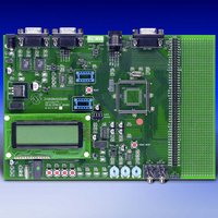
BOARD DEMO DSPICDEM 1.1 GEN PURP
Manufacturer
Microchip Technology
Datasheet
1.DM300014.pdf
(72 pages)
Specifications of DM300014
Processor To Be Evaluated
PIC30F
Data Bus Width
16 bit
Interface Type
RS-485, CAN, SPI
Lead Free Status / RoHS Status
Lead free / RoHS Compliant
Lead Free Status / RoHS Status
Lead free / RoHS Compliant, Lead free / RoHS Compliant


2003 Microchip Technology Inc.
4.1.3
Signals for the RS-485/RS-422 port are available on the 6-pin terminal block labeled
TB1. The terminal block can be reconfigured from RS-485 to RS-422 by removing the
jumper on J7. Inserting jumper J6 will terminate the bus with a 120-ohm resistor.
The RX485 and TX485 lines of the MAX489E can be tied to the dsPIC UART channel 1
U1RX and U1TX pins by moving the jumper on J4 to the TX485/RX485 position.
MAX489E receiver and driver output enables are controlled by port pins RG0 and RG1,
respectively.
The schematic of the RS-485 and RS-422 ports is shown in Figure A-4: “dsPICDEM
1.1 Development Board Schematic (Sheet 3 of 5)”.
4.1.4
Temperature sensor U9 is a -40°C to +125°C linear output TC1047A connected to
analog channel AN8 of the dsPIC device. The output of the temperature sensor is fed
through a second-order low-pass filter before connection to the dsPIC device. The
low-pass filter cutoff frequency is set at 10 Hz. The output voltage range for the
TC1047A is typically 750 mV at +25°C. The TC1047A exhibits a typical 10 mV/C
voltage slope.
The schematic of the temperature sensor is shown in Figure A-6: “dsPICDEM 1.1
Development Board Schematic (Sheet 5 of 5)”.
4.1.5
Three 5 kOhm potentiometers are connected to analog channels AN4, AN5 and AN6.
The voltage output range for each potentiometer is between 0V DC and 5V DC. The
voltage source is provided by VR2, which is a separate voltage source for all the analog
components on the development board.
The schematic of the analog potentiometers is shown in Figure A-6: “dsPICDEM 1.1
Development Board Schematic (Sheet 5 of 5)”.
4.1.6
Switches SW1-SW4 are connected to port pins RA12-RA15, respectively, on the dsPIC
device. The signal lines are normally pulled up to +5V DC through 10 kOhm resistors.
Pressing the switch will short the line to ground. Port pins RA12-RA15 are configured
as the INT1-INT4 external interrupt pins.
The schematic of the push button switches is shown in Figure A-6: “dsPICDEM 1.1
Development Board Schematic (Sheet 5 of 5)”.
4.1.7
Four red LEDs, LED1-LED4, are connected to port pins RD0-RD3, respectively, on the
dsPIC device. The LED anodes are tied to V
The schematic of the LEDs is shown in Figure A-6: “dsPICDEM 1.1 Development
Board Schematic (Sheet 5 of 5)”.
dsPICDEM™ 1.1 Development Hardware
RS-485/RS-422 Port
Temperature Sensor
Analog Potentiometers
Push Button Switches
LEDs
Advance Information
DD
through a 1.2 KOhm resistor.
DS70099B-page 43
Related parts for DM300014
Image
Part Number
Description
Manufacturer
Datasheet
Request
R

Part Number:
Description:
Manufacturer:
Microchip Technology Inc.
Datasheet:
Part Number:
Description:
Manufacturer:
Microchip Technology Inc.
Datasheet:
Part Number:
Description:
Manufacturer:
Microchip Technology Inc.
Datasheet:
Part Number:
Description:
Manufacturer:
Microchip Technology Inc.
Datasheet:
Part Number:
Description:
Manufacturer:
Microchip Technology Inc.
Datasheet:
Part Number:
Description:
Manufacturer:
Microchip Technology Inc.
Datasheet:
Part Number:
Description:
Manufacturer:
Microchip Technology Inc.
Datasheet:
Part Number:
Description:
Manufacturer:
Microchip Technology Inc.
Datasheet: