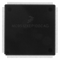
MC9S12XEP100CAG Freescale Semiconductor, MC9S12XEP100CAG Datasheet - Page 383

MC9S12XEP100CAG
Manufacturer Part Number
MC9S12XEP100CAG
Description
IC MCU 16BIT 1M FLASH 144-LQFP
Manufacturer
Freescale Semiconductor
Series
HCS12r
Datasheet
1.MC9S12XEP768CAL.pdf
(1328 pages)
Specifications of MC9S12XEP100CAG
Core Processor
HCS12X
Core Size
16-Bit
Speed
50MHz
Connectivity
CAN, EBI/EMI, I²C, IrDA, SCI, SPI
Peripherals
LVD, POR, PWM, WDT
Number Of I /o
119
Program Memory Size
1MB (1M x 8)
Program Memory Type
FLASH
Eeprom Size
4K x 8
Ram Size
64K x 8
Voltage - Supply (vcc/vdd)
1.72 V ~ 5.5 V
Data Converters
A/D 24x12b
Oscillator Type
External
Operating Temperature
-40°C ~ 85°C
Package / Case
144-LQFP
Processor Series
S12XE
Core
HCS12
Data Bus Width
16 bit
Data Ram Size
64 KB
Interface Type
CAN/SCI/SPI
Maximum Clock Frequency
50 MHz
Number Of Programmable I/os
119
Number Of Timers
25
Maximum Operating Temperature
+ 85 C
Mounting Style
SMD/SMT
3rd Party Development Tools
EWHCS12
Development Tools By Supplier
KIT33812ECUEVME, EVB9S12XEP100, DEMO9S12XEP100
Minimum Operating Temperature
- 40 C
On-chip Adc
24-ch x 12-bit
Cpu Family
HCS12X
Device Core Size
16b
Frequency (max)
50MHz
Total Internal Ram Size
64KB
# I/os (max)
119
Number Of Timers - General Purpose
25
Operating Supply Voltage (typ)
1.8/2.8/5V
Operating Supply Voltage (max)
1.98/2.9/5.5V
Operating Supply Voltage (min)
1.72/2.7/3.13V
Instruction Set Architecture
RISC
Operating Temp Range
-40C to 85C
Operating Temperature Classification
Industrial
Mounting
Surface Mount
Pin Count
144
Package Type
LQFP
Package
144LQFP
Family Name
HCS12X
Maximum Speed
50 MHz
Operating Supply Voltage
1.8|2.8|5 V
For Use With
EVB9S12XEP100 - BOARD EVAL FOR MC9S12XEP100DEMO9S12XEP100 - BOARD DEMO FOR MC9S12XEP100
Lead Free Status / RoHS Status
Lead free / RoHS Compliant
Available stocks
Company
Part Number
Manufacturer
Quantity
Price
Company:
Part Number:
MC9S12XEP100CAG
Manufacturer:
FREESCAL
Quantity:
244
Company:
Part Number:
MC9S12XEP100CAG
Manufacturer:
Freescale Semiconductor
Quantity:
10 000
- Current page: 383 of 1328
- Download datasheet (9Mb)
10.6.2
Debug mode can only be left by setting the XGDBG bit to "0". If a thread is active (XGCHID has not been
cleared in debug mode), program execution will resume at the value of XGPC.
10.7
In order to protect XGATE application code on secured S12X devices, a few restrictions in the debug
features have been made. These are:
Freescale Semiconductor
Because of an order from the United States International Trade Commission, BGA-packaged product lines and partnumbers
indicated here currently are not available from Freescale for import or sale in the United States prior to September 2010
2. Software breakpoints
3. Tagged Breakpoints
4. Forced Breakpoints
•
•
•
Writing a "1" to XGDBG and XGDBGM in the same write access causes the XGATE to enter
debug mode upon completion of the current instruction.
XGATE programs which are stored in the internal RAM allow the use of software breakpoints. A
software breakpoint is set by replacing an instruction of the program code with the "BRK"
instruction.
As soon as the program execution reaches the "BRK" instruction, the XGATE enters debug mode.
Additionally a software breakpoint request is sent to the S12X_DBG module (see section 4.9 of
the S12X_DBG Section).
Upon entering debug mode, the program counter will point to the "BRK" instruction. The other
RISC core registers will hold the result of the previous instruction.
To resume program execution, the "BRK" instruction must be replaced by the original instruction
before leaving debug mode.
The S12X_DBG module is able to place tags on fetched opcodes. The XGATE is able to enter
debug mode right before a tagged opcode is executed (see section 4.9 of the S12X_DBG Section).
Upon entering debug mode, the program counter will point to the tagged instruction. The other
RISC core registers will hold the result of the previous instruction.
Forced breakpoints are triggered by the S12X_DBG module (see section 4.9 of the S12X_DBG
Section). When a forced breakpoint occurs, the XGATE will enter debug mode upon completion
of the current instruction.
Registers XGCCR, XGPC, and XGR1–XGR7 will read zero on a secured device
Registers XGCCR, XGPC, and XGR1–XGR7 can not be written on a secured device
Single stepping is not possible on a secured device
Security
Leaving Debug Mode
After writing to the XGDBG bit the XGATE will not immediately enter
debug mode. Depending on the instruction that is executed at this time there
may be a delay of several clock cycles. The XGDBG will read "0" until
debug mode is entered.
MC9S12XE-Family Reference Manual Rev. 1.23
NOTE
Chapter 10 XGATE (S12XGATEV3)
383
Related parts for MC9S12XEP100CAG
Image
Part Number
Description
Manufacturer
Datasheet
Request
R
Part Number:
Description:
Manufacturer:
Freescale Semiconductor, Inc
Datasheet:
Part Number:
Description:
Manufacturer:
Freescale Semiconductor, Inc
Datasheet:
Part Number:
Description:
Manufacturer:
Freescale Semiconductor, Inc
Datasheet:
Part Number:
Description:
Manufacturer:
Freescale Semiconductor, Inc
Datasheet:
Part Number:
Description:
Manufacturer:
Freescale Semiconductor, Inc
Datasheet:
Part Number:
Description:
Manufacturer:
Freescale Semiconductor, Inc
Datasheet:
Part Number:
Description:
Manufacturer:
Freescale Semiconductor, Inc
Datasheet:
Part Number:
Description:
Manufacturer:
Freescale Semiconductor, Inc
Datasheet:
Part Number:
Description:
Manufacturer:
Freescale Semiconductor, Inc
Datasheet:
Part Number:
Description:
Manufacturer:
Freescale Semiconductor, Inc
Datasheet:
Part Number:
Description:
Manufacturer:
Freescale Semiconductor, Inc
Datasheet:
Part Number:
Description:
Manufacturer:
Freescale Semiconductor, Inc
Datasheet:
Part Number:
Description:
Manufacturer:
Freescale Semiconductor, Inc
Datasheet:
Part Number:
Description:
Manufacturer:
Freescale Semiconductor, Inc
Datasheet:
Part Number:
Description:
Manufacturer:
Freescale Semiconductor, Inc
Datasheet:


