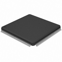
AT32UC3A0512-ALTTA Atmel, AT32UC3A0512-ALTTA Datasheet - Page 318

AT32UC3A0512-ALTTA
Manufacturer Part Number
AT32UC3A0512-ALTTA
Description
IC MCU AVR32 512K FLASH 144LQFP
Manufacturer
Atmel
Series
AVR®32 UC3r
Datasheet
1.ATEVK1104.pdf
(826 pages)
Specifications of AT32UC3A0512-ALTTA
Core Processor
AVR
Core Size
32-Bit
Speed
66MHz
Connectivity
EBI/EMI, Ethernet, I²C, SPI, SSC, UART/USART, USB OTG
Peripherals
Brown-out Detect/Reset, POR, PWM, WDT
Number Of I /o
109
Program Memory Size
512KB (512K x 8)
Program Memory Type
FLASH
Ram Size
64K x 8
Voltage - Supply (vcc/vdd)
1.65 V ~ 1.95 V
Data Converters
A/D 8x10b
Oscillator Type
Internal
Operating Temperature
-40°C ~ 85°C
Package / Case
144-LQFP
Lead Free Status / RoHS Status
Lead free / RoHS Compliant
Eeprom Size
-
Available stocks
Company
Part Number
Manufacturer
Quantity
Price
- Current page: 318 of 826
- Download datasheet (20Mb)
Figure 26-19. FSK Modulator Output
26.7.4
Figure 26-20. Synchronous Mode Character Reception
26.7.4.1
32058J–AVR32–04/11
Uptstream Frequencies
unipolar output
FSK Modulator
default polarity
[F0, F0+offset]
NRZ stream
Synchronous Receiver
Manchester
Receiver Operations
encoded
Output
data
Example: 8-bit, Parity Enabled 1 Stop
Baud Rate
Sampling
Clock
RXD
Txd
1
In synchronous mode (SYNC = 1), the receiver samples the RXD signal on each rising edge of
the Baud Rate Clock. If a low level is detected, it is considered as a start. All data bits, the parity
bit and the stop bits are sampled and the receiver waits for the next start bit. Synchronous mode
operations provide a high speed transfer capability.
Configuration fields and bits are the same as in asynchronous mode.
Figure 26-20 on page 318
When a character reception is completed, it is transferred to the Receive Holding Register
(RHR) and the RXRDY bit in the Status Register (CSR) rises. If a character is completed while
the RXRDY is set, the OVRE (Overrun Error) bit is set. The last character is transferred into
RHR and overwrites the previous one. The OVRE bit is cleared by writing the Control Register
(CR) with the RSTSTA (Reset Status) bit at 1.
Start
D0
D1
0
illustrates a character reception in synchronous mode.
D2
D3
D4
0
D5
D6
D7
Parity Bit
Stop Bit
1
AT32UC3A
318
Related parts for AT32UC3A0512-ALTTA
Image
Part Number
Description
Manufacturer
Datasheet
Request
R

Part Number:
Description:
MCU, MPU & DSP Development Tools KICKSTART KIT FOR AT32UC3A
Manufacturer:
IAR Systems

Part Number:
Description:
DEV KIT FOR AVR/AVR32
Manufacturer:
Atmel
Datasheet:

Part Number:
Description:
INTERVAL AND WIPE/WASH WIPER CONTROL IC WITH DELAY
Manufacturer:
ATMEL Corporation
Datasheet:

Part Number:
Description:
Low-Voltage Voice-Switched IC for Hands-Free Operation
Manufacturer:
ATMEL Corporation
Datasheet:

Part Number:
Description:
MONOLITHIC INTEGRATED FEATUREPHONE CIRCUIT
Manufacturer:
ATMEL Corporation
Datasheet:

Part Number:
Description:
AM-FM Receiver IC U4255BM-M
Manufacturer:
ATMEL Corporation
Datasheet:

Part Number:
Description:
Monolithic Integrated Feature Phone Circuit
Manufacturer:
ATMEL Corporation
Datasheet:

Part Number:
Description:
Multistandard Video-IF and Quasi Parallel Sound Processing
Manufacturer:
ATMEL Corporation
Datasheet:

Part Number:
Description:
High-performance EE PLD
Manufacturer:
ATMEL Corporation
Datasheet:

Part Number:
Description:
8-bit Flash Microcontroller
Manufacturer:
ATMEL Corporation
Datasheet:

Part Number:
Description:
2-Wire Serial EEPROM
Manufacturer:
ATMEL Corporation
Datasheet:


