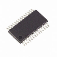
MAXQ3108-FFN+ Maxim Integrated Products, MAXQ3108-FFN+ Datasheet - Page 21

MAXQ3108-FFN+
Manufacturer Part Number
MAXQ3108-FFN+
Description
IC MCU DUAL-CORE 16BIT 28-TSSOP
Manufacturer
Maxim Integrated Products
Series
MAXQ™r
Datasheet
1.MAXQ3108-FFN.pdf
(64 pages)
Specifications of MAXQ3108-FFN+
Core Processor
RISC
Core Size
16-Bit
Speed
10MHz
Connectivity
I²C, SPI, UART/USART
Peripherals
POR, PWM, WDT
Number Of I /o
21
Program Memory Size
64KB (32K x 16)
Program Memory Type
FLASH
Ram Size
11K x 8
Voltage - Supply (vcc/vdd)
1.8 V ~ 3.6 V
Oscillator Type
External
Operating Temperature
-40°C ~ 85°C
Package / Case
28-TSSOP
Processor Series
MAXQ
Core
RISC
Data Bus Width
16 bit
Data Ram Size
2 KB
Interface Type
I2C, JTAG, SPI
Maximum Clock Frequency
10 MHz
Number Of Programmable I/os
22
Number Of Timers
2
Operating Supply Voltage
3.6 V
Maximum Operating Temperature
+ 85 C
Mounting Style
SMD/SMT
Minimum Operating Temperature
- 40 C
Lead Free Status / RoHS Status
Lead free / RoHS Compliant
Eeprom Size
-
Data Converters
-
Lead Free Status / Rohs Status
Lead free / RoHS Compliant
ADCN.13: IF32E
ADCN.14: IF54E
ADCN.15: IFCSEL
ADCC (12h, 00h)
Initialization:
Read/Write Access:
ADCC.[15:0]:
MSTC (13h, 00h)
Initialization:
Read/Write Access:
MSTC.0: MD0SNC
MSTC.1: MD1SNC
MSTC.2: MD2SNC
MSTC.3: Reserved
______________________________________________________________________________________
Low-Power, Dual-Core Microcontroller
ADC Interrupt Flags 3 and 2 Enable. This bit serves as the local interrupt enable for the ADC cubic
sinc filter output buffers 3 and 2.
ADC Interrupt Flags 5 and 4 Enable. This bit serves as the local interrupt enable for the ADC cubic
sinc filter output buffers 5 and 4.
ADC Interrupt Flag Core Select. This bit controls the routing and the ability to clear the ADC
interrupt flags. When this bit is configured to 0, the ADC interrupt capability and the ability to clear
the associated flags belongs to the UserCore. When this bit is configured to 1, only the DSPCore
can be interrupted and has the ability to clear the interrupt flags. This bit is write accessible only to
the UserCore.
Analog-to-Digital Clock Correction Register
This register is reset to 0000h.
Unrestricted read access.
ADC Clock Correction Value 15:0. This value reflects the count (measurement) of decoder sync
bits during the predefined duration of 32kHz x 2
The clock correction facility is enabled on any write to the CCSL[1:0] bits (other than the 11b
disable request). The ADCC register reads 0000h to indicate a busy (measuring) condition until the
measurement completes, at which point, the ADCC register is updated.
Manchester Decoder Status Register
This register is reset to 30h.
Unrestricted read access. Unrestricted write access to bits 5:4 (see description).
Manchester Decoder 0 Synchronization Status Bit. This bit reflects the synchronization status of
Manchester decoder 0. When the decoder has achieved synchronization, this bit is set to 1. When
the decoder cannot or has not yet detected the required alternating synchronization bit in the
Manchester bit stream, this bit is cleared to 0. Once synchronized, loss of synchronization is
signaled (i.e., bit is cleared) once three sync bit errors are detected in 10 frames. If fewer than three
errors are detected in 10 frames, the synchronization bit error counter restarts on the next sync bit
error.
Manchester Decoder 1 Synchronization Status Bit. This bit reflects the synchronization status of
Manchester decoder 1. When the decoder has achieved synchronization, this bit is set to 1. When
the decoder cannot or has not yet detected the required alternating synchronization bit in the
Manchester bit stream, this bit is cleared to 0. Once synchronized, loss of synchronization is
signaled (i.e., bit is cleared) once three sync bit errors are detected in 10 frames. If fewer than three
errors are detected in 10 frames, the synchronization bit error counter restarts on the next sync bit
error.
Manchester Decoder 2 Synchronization Status Bit. This bit reflects the synchronization status of
Manchester decoder 2. When the decoder has achieved synchronization, this bit is set to 1. When
the decoder cannot or has not yet detected the required alternating synchronization bit in the
Manchester bit stream, this bit is cleared to 0.
Reserved. Reads return 0.
Special Function Register Bit Descriptions (continued)
9
clocks for the decoder selected by CCSL[1:0].
21


