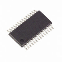
MAXQ3108-FFN+ Maxim Integrated Products, MAXQ3108-FFN+ Datasheet - Page 27

MAXQ3108-FFN+
Manufacturer Part Number
MAXQ3108-FFN+
Description
IC MCU DUAL-CORE 16BIT 28-TSSOP
Manufacturer
Maxim Integrated Products
Series
MAXQ™r
Datasheet
1.MAXQ3108-FFN.pdf
(64 pages)
Specifications of MAXQ3108-FFN+
Core Processor
RISC
Core Size
16-Bit
Speed
10MHz
Connectivity
I²C, SPI, UART/USART
Peripherals
POR, PWM, WDT
Number Of I /o
21
Program Memory Size
64KB (32K x 16)
Program Memory Type
FLASH
Ram Size
11K x 8
Voltage - Supply (vcc/vdd)
1.8 V ~ 3.6 V
Oscillator Type
External
Operating Temperature
-40°C ~ 85°C
Package / Case
28-TSSOP
Processor Series
MAXQ
Core
RISC
Data Bus Width
16 bit
Data Ram Size
2 KB
Interface Type
I2C, JTAG, SPI
Maximum Clock Frequency
10 MHz
Number Of Programmable I/os
22
Number Of Timers
2
Operating Supply Voltage
3.6 V
Maximum Operating Temperature
+ 85 C
Mounting Style
SMD/SMT
Minimum Operating Temperature
- 40 C
Lead Free Status / RoHS Status
Lead free / RoHS Compliant
Eeprom Size
-
Data Converters
-
Lead Free Status / Rohs Status
Lead free / RoHS Compliant
PWCN.2: ECLKO
PWCN.[4:3]: Reserved
PWCN.5: RSTD
PWCN.6: REGEN
PWCN.7: BOD
PWCN.[9:8]: Reserved
PWCN.10: ENDSP
PWCN.[15:11]: Reserved
BB0 (10h, 01h)
Initialization:
Read/Write Access:
BB0.[15:0]:
BB1 (11h, 01h)
BB2 (12h, 01h)
BB3 (13h, 01h)
BB4 (14h, 01h)
BB5 (15h, 01h)
BB6 (16h, 01h)
BB7 (17h, 01h)
______________________________________________________________________________________
Low-Power, Dual-Core Microcontroller
Enable Clock Output Pin. Setting this bit to 1 enables the output of the DSPCore undivided system
clock on P2.2. The P2.2 pin also serves as the SPI serial clock (SCLK) special function. The SPI
hardware should not be used when the CLKO output is enabled. The ECLKO bit can be used in the
hybrid configuration to allow the test system clock to be routed to the DS8102 CLKIO pin.
Reserved. Reads return 0.
Reset Pin Disable. When set to a logic 1, the reset input function is disconnected from the external
RST pin. The port pin can then be used for other purposes. When cleared to a logic 0, the reset
input function is connected to the external pin; however, the port directional and output controls
still apply. This bit defaults to 0 on power-on reset only.
Regulator Enable. When set to 1, the internal regulator remains powered on when the device is
placed in stop mode. When cleared to 0, the internal regulator is shut down to conserve power. The
regulator is always enabled outside of stop mode, independent of the REGEN bit setting.
Brownout-Detection Disable. This bit determines whether the brownout detection is enabled in stop
mode when the regulator is off (REGEN = 0). When the regulator is enabled (as in normal operation
or when REGEN = 1 in stop mode), the brownout detection is always enabled, independent of the
BOD bit setting. Otherwise, when set to 1, the brownout reset detection for V
the device is placed into stop mode. When placed into stop mode with BOD = 1 and REGEN = 0,
the brownout reset comparator is shut down. When configured to 0 with REGEN = 0, the brownout-
detection function is enabled for detecting the condition V
Reserved. Reads return 0.
Enable DSPCore. This active-high bit is cleared to 0 on any UserCore reset and when the
UserCore invokes stop mode. When cleared, the DSPCore is completely disabled. This bit is
read/write accessible only to the UserCore so that it controls when the slave DSPCore is allowed to
operate. When this bit is written to 1, the DSPCore is removed from reset and is allowed to operate.
Reserved. Reads return 0.
Battery-Backed Register 0 (16-Bit Register)
This register is battery backed through POR so long as V
is indeterminate on the very first POR and must be configured initially by the user. This register is
unaffected by other resets.
Unrestricted read/write access.
Battery-Backed Register 0 Bits 15:0. This register is intended for quick and convenient storage of
critical data through V
external serial NV memory).
See the BB0 register for description.
Special Function Register Bit Descriptions (continued)
DD
power outages (avoiding the more time-consuming write attempts to
BAT(MIN)
DD
< V
RST
< V
during stop mode.
BAT
< V
DD
BAT(MAX)
is disabled when
; however, it
27


