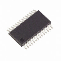
MAXQ3108-FFN+ Maxim Integrated Products, MAXQ3108-FFN+ Datasheet - Page 62

MAXQ3108-FFN+
Manufacturer Part Number
MAXQ3108-FFN+
Description
IC MCU DUAL-CORE 16BIT 28-TSSOP
Manufacturer
Maxim Integrated Products
Series
MAXQ™r
Datasheet
1.MAXQ3108-FFN.pdf
(64 pages)
Specifications of MAXQ3108-FFN+
Core Processor
RISC
Core Size
16-Bit
Speed
10MHz
Connectivity
I²C, SPI, UART/USART
Peripherals
POR, PWM, WDT
Number Of I /o
21
Program Memory Size
64KB (32K x 16)
Program Memory Type
FLASH
Ram Size
11K x 8
Voltage - Supply (vcc/vdd)
1.8 V ~ 3.6 V
Oscillator Type
External
Operating Temperature
-40°C ~ 85°C
Package / Case
28-TSSOP
Processor Series
MAXQ
Core
RISC
Data Bus Width
16 bit
Data Ram Size
2 KB
Interface Type
I2C, JTAG, SPI
Maximum Clock Frequency
10 MHz
Number Of Programmable I/os
22
Number Of Timers
2
Operating Supply Voltage
3.6 V
Maximum Operating Temperature
+ 85 C
Mounting Style
SMD/SMT
Minimum Operating Temperature
- 40 C
Lead Free Status / RoHS Status
Lead free / RoHS Compliant
Eeprom Size
-
Data Converters
-
Lead Free Status / Rohs Status
Lead free / RoHS Compliant
Low-Power, Dual-Core Microcontroller
Bit 11: TBCR. Setting this bit enables PWM mode. If
this bit is set (and TBCS is clear), the TBB pin is driven
to 0 when TB0V = TB0C and driven to 1 when TB0V =
TB0R. Setting both TBCS and TBCR causes TBB to tog-
gle when TB0V = TB0C.
Bit 12: TBCS. Setting this bit enables PWM mode. If
this bit is set (and TBCR is clear), the TBB pin is driven
to 1 when TB0V = TB0C and driven to 0 when TB0V =
TB0R. Setting both TBCS and TBCR causes TBB to tog-
gle when TB0V = TB0C.
Bit 15: C/ B. When clear, the timer is configured as a
timer (that is, it counts clock pulses from the prescaled
system clock.) When set, the timer is configured as a
counter; that is, it counts transitions on the TBA pin.
Case 1: Output 1kHz square wave on TBA.
In this instance, reload the timer at a 500µs interval
(since a 1kHz square wave has an edge every 500µs.
Since the default UserCore clock is 5.014MHz, the total
divisor should be 5014kHz/2kHz = 2507. Thus, a
prescaler value of 1 and a TB0R value of 2507
(0x09CB) provides the necessary timing.
The procedure is as follows:
• Load TB0R with 0x09CB.
• Load TB0CN with 0x0024. This (1) sets the timer to
Case 2: Configure a PWM output with one part in
1000 resolution. Frequency is not critical.
In this instance, configure TB0R with a value of 1000.
Configure TB0CN with 0x0804. This (1) sets the timer to
timer mode, (2) enables PWM mode, (3) sets a
prescaler divisor of 1, (4) disables the TXFB trigger, (5)
disables square-wave output, (6) sets reload mode,
and (7) disables interrupts.
Writing a value to TB0C sets the duty cycle of the output
on TBB. When the TB0C value is 100, for example, the
timer counts from 0 to 99 with the output high. When the
timer reaches 100, the TB0C value is a match and the
output goes low. The timer continues to run until it reach-
es 1000, at which time it switches low and reloads to 0.
62
timer mode, (2) disables PWM mode, (3) sets a
prescaler divisor of 1, (4) disables the TXFB trigger,
(5) enables square-wave output, (6) sets reload
mode, and (7) disables any interrupts in the timer.
______________________________________________________________________________________
Timer B Use-Case Scenarios
The MAXQ3108 contains one multiply-accumulate unit
for each CPU core. Each of these units can multiply two
16-bit numbers (signed or unsigned) in a single CPU
cycle, and then accumulate the result to a 48-bit accu-
mulator in a second cycle. Details on the multiply-accu-
mulate units are available in Section 12 of the MAXQ
Family User’s Guide .
The real-time clock is a 32-bit time-of-day clock that
supports interrupt generation based on time intervals
and time-of-day alarms. It is driven from the 32,768Hz
crystal oscillator and operates even when the UserCore
is in stop mode.
For information on the real-time clock module, refer to
Section 14 of the MAXQ Family User’s Guide .
The DSPCore has access to two precision, programma-
ble pulse generators. Pulse generation is critical in
electricity meters and other utility-based applications.
The principle of the pulse generator is simple: an output
port is conditioned on a 22-bit counter so that when the
counter is 0, the output port operates normally (that is,
when a bit value is written to the port, the state of the
pin changes); but when the counter is running, the pin
is held at its previous state regardless of what value is
written to it. The moment the counter reaches 0, howev-
er, the new value is transferred to the pin.
To use the pulse generator, write a 1 to the port and
write a value to the counter. The counter begins count-
ing down. While the counter is running, write a 0 to the
port. Because the counter is running, the 0 is not imme-
diately reflected on the pin. Only when the counter
reaches 0 does the “0” level transfer to the pin. The
practical value of this is the amount of time that the pin
has been high is exactly a function of the value written
to the counter.
In the MAXQ3108, the counter is 22 bits wide, but only
the high-order 16 bits are writable. The other 6 bits are
cleared on any write. Thus, the maximum value that can
be written to the register is 0x3FFFC0, or, at the default
clock rate of the DSPCore (10.027MHz) about 418ms.
Programmable Pulse Generators
Multiply-Accumulate Unit
Real-Time Clock


