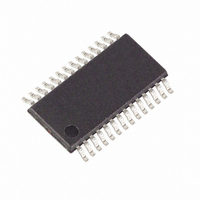
MAXQ3108-FFN+ Maxim Integrated Products, MAXQ3108-FFN+ Datasheet - Page 28

MAXQ3108-FFN+
Manufacturer Part Number
MAXQ3108-FFN+
Description
IC MCU DUAL-CORE 16BIT 28-TSSOP
Manufacturer
Maxim Integrated Products
Series
MAXQ™r
Datasheet
1.MAXQ3108-FFN.pdf
(64 pages)
Specifications of MAXQ3108-FFN+
Core Processor
RISC
Core Size
16-Bit
Speed
10MHz
Connectivity
I²C, SPI, UART/USART
Peripherals
POR, PWM, WDT
Number Of I /o
21
Program Memory Size
64KB (32K x 16)
Program Memory Type
FLASH
Ram Size
11K x 8
Voltage - Supply (vcc/vdd)
1.8 V ~ 3.6 V
Oscillator Type
External
Operating Temperature
-40°C ~ 85°C
Package / Case
28-TSSOP
Processor Series
MAXQ
Core
RISC
Data Bus Width
16 bit
Data Ram Size
2 KB
Interface Type
I2C, JTAG, SPI
Maximum Clock Frequency
10 MHz
Number Of Programmable I/os
22
Number Of Timers
2
Operating Supply Voltage
3.6 V
Maximum Operating Temperature
+ 85 C
Mounting Style
SMD/SMT
Minimum Operating Temperature
- 40 C
Lead Free Status / RoHS Status
Lead free / RoHS Compliant
Eeprom Size
-
Data Converters
-
Lead Free Status / Rohs Status
Lead free / RoHS Compliant
Low-Power, Dual-Core Microcontroller
28
RTRM (18h, 01h)
Initialization:
Read/Write Access:
RTRM.[6:0]: TRM[6:0]
RTRM.7: TSGN
RCNT (19h, 01h)
Initialization:
Read/Write Access:
RCNT.0: RTCE
RCNT.1: ADE
RCNT.2: ASE
RCNT.3: BUSY
RCNT.4: RDY
RCNT.5: RDYE
______________________________________________________________________________________
Real-Time Clock Trim Register (8-Bit Register)
This register is battery backed through POR so long as V
is indeterminate on the very first POR and must be configured initially by the user. This register is
unaffected by other resets.
Unrestricted read, write access only when the WE = 1 and BUSY = 0. An attempted write operation
is not complete until hardware clears the BUSY bit.
RTC Trim Calibration Register Bits 6:0. These register bits provide a binary value between 00h–
7Fh, which is used for adjusting 32K clocks insertion/removal. At every 10-second interval, the
number of 32K clocks equal to the RTRM[6:0] numeric value is inserted/removed from the RTC
counter depending on the value in the TSGN bit. The trim bits are write protected by WE. WE must
be set to 1 for the bits to be updated.
RTC Trim Sign Bit. This register bit selects whether 32K clocks are inserted (TSGN = 0) or
removed (TSGN = 1).
Real-Time Clock Control Register (16-Bit Register)
This register is initialized to 0sssss000000100sb on all forms of reset. Bits 14–10 and bit 0 are
battery backed through POR so long as V
are indeterminate on the very first POR and must be configured by the user, but are unaffected by
other resets.
Unrestricted read. Bit 0 (RTCE) is write accessible only when WE = 1 and BUSY = 0. Bits 3 (BUSY)
and 13 (32KRDY) are read-only. Bit 4 can be cleared to 0 when RTCE = 1; it can never be set to 1
by software. Bit 15 is unrestricted write. All other bits are write accessible only when BUSY = 0.
Real-Time Clock Enable. The RTCE is the real-time enable bit. Setting this bit to logic 1 activates
the clocking by allowing the divided clock to the ripple counters. Clearing this bit to logic 0
disables the clock.
Alarm Time-of-Day Enable. The ADE bit is the RTC’s time-of-day alarm enable and must be set to
logic 1 for the alarm to generate a system interrupt request. When the ADE is cleared to logic 0, the
time-of-day alarm is disabled; no interrupt is generated even the alarm is set.
Alarm Subsecond Enable. The ASE bit is the RTC’s subsecond timer enable and must be set to
logic 1 for the subsecond alarm to generate a system interrupt request. When the ASE is cleared to
logic 0, the subsecond alarm is disabled; no interrupt is generated even the alarm is set.
RTC Busy. This bit is set to 1 by hardware when any of the following conditions occur:
For conditions 2) and 3), the write or change should not be considered complete until hardware
clears the BUSY bit. This is an indication that a 32kHz synchronized version of the register bit(s) is
in place.
RTC Ready. This bit is set to 1 by hardware when the RTC count registers update. It can be cleared
to 0 by software at any time. It is also cleared to 0 by hardware just prior to an update of the RTC
count register. This bit can generate an interrupt if the RDYE bit is set to 1.
RTC Ready Enable. Setting this bit to 1 allows a system interrupt to be generated when RDY
becomes active (if interrupts are enabled globally and modularly). Clearing this bit to 0 disables
the RDY interrupt.
1) System reset.
2) Software writes to RTC count registers or trim register.
3) Software changes RTCE, ASE, or ADE.
Special Function Register Bit Descriptions (continued)
BAT(MIN)
< V
BAT
BAT(MIN)
< V
BAT(MAX)
< V
BAT
. These battery-backed bits
< V
BAT(MAX)
; however, it


