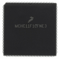
MCHC11F1CFNE3 Freescale Semiconductor, MCHC11F1CFNE3 Datasheet - Page 53

MCHC11F1CFNE3
Manufacturer Part Number
MCHC11F1CFNE3
Description
IC MCU 8BIT 1K RAM 68-PLCC
Manufacturer
Freescale Semiconductor
Series
HC11r
Specifications of MCHC11F1CFNE3
Core Processor
HC11
Core Size
8-Bit
Speed
3MHz
Connectivity
SCI, SPI
Peripherals
POR, WDT
Number Of I /o
30
Program Memory Type
ROMless
Eeprom Size
512 x 8
Ram Size
1K x 8
Voltage - Supply (vcc/vdd)
4.75 V ~ 5.25 V
Data Converters
A/D 8x8b
Oscillator Type
Internal
Operating Temperature
-40°C ~ 85°C
Package / Case
68-PLCC
A/d Inputs
8-Channel, 8-Bit
Eeprom Memory
512 Bytes
Input Output
30
Interface
SCI/SPI
Memory Type
EPROM
Number Of Bits
8
Package Type
68-pin PLCC
Programmable Memory
0 Bytes
Timers
3-16-bit
Voltage, Range
3-5.5 V
Controller Family/series
68HC11
No. Of I/o's
30
Eeprom Memory Size
512Byte
Ram Memory Size
1KB
Cpu Speed
3MHz
No. Of Timers
1
Embedded Interface Type
SCI, SPI
Rohs Compliant
Yes
Processor Series
HC11F
Core
HC11
Data Bus Width
8 bit
Program Memory Size
512 B
Data Ram Size
1 KB
Interface Type
SCI, SPI
Maximum Clock Frequency
3 MHz
Number Of Timers
1
Maximum Operating Temperature
+ 85 C
Mounting Style
SMD/SMT
Minimum Operating Temperature
- 40 C
On-chip Adc
8 bit, 8 Channel
Lead Free Status / RoHS Status
Lead free / RoHS Compliant
Program Memory Size
-
Lead Free Status / Rohs Status
RoHS Compliant part
Available stocks
Company
Part Number
Manufacturer
Quantity
Price
Company:
Part Number:
MCHC11F1CFNE3
Manufacturer:
FREESCALE
Quantity:
5 530
Company:
Part Number:
MCHC11F1CFNE3
Manufacturer:
FREESCALE
Quantity:
5 530
Company:
Part Number:
MCHC11F1CFNE3
Manufacturer:
Freescale Semiconductor
Quantity:
10 000
Company:
Part Number:
MCHC11F1CFNE3R
Manufacturer:
Freescale Semiconductor
Quantity:
10 000
11 Analog-to-Digital Converter
MC68HC11F1/FC0
MC68HC11FTS/D
PE0
AN0
PE1
AN1
PE2
AN2
PE6
AN6
PE7
AN7
PE3
AN3
PE4
AN4
PE5
AN5
The MC68HC11F1 analog-to-digital (A/D) converter system uses an all-capacitive charge-redistribution
technique to convert analog signals to digital values. The A/D system is an 8-channel, 8-bit, multiplexed-
input, successive-approximation converter, accurate to 1 least significant bit (LSB). Because the ca-
pacitive charge redistribution technique used includes a built-in sample-and-hold, no external sample-
and-hold is required.
Dedicated lines V
rates of 750 kHz or below must use an internal RC oscillator. The CSEL bit in the OPTION register se-
lects the clock source for the A/D system. (The CSEL bit is described in 11.3 A/D Registers, page 56.)
A multiplexer allows the single A/D converter to select one of 16 analog signals, as shown in Table 24.
ANALOG
ADR1 A/D RESULT 1
MUX
RH
and V
The A/D converter is present on the MC68HC11F1 only.
Freescale Semiconductor, Inc.
RESULT
For More Information On This Product,
RL
Figure 14 A/D Converter Block Diagram
ADR2 A/D RESULT 2
provide the reference supply voltage inputs. Systems operating at clock
SUCCESSIVE APPROXIMATION
WITH SAMPLE AND HOLD
REGISTER AND CONTROL
8-BIT CAPACITIVE DAC
Go to: www.freescale.com
RESULT REGISTER INTERFACE
NOTE
ADR3 A/D RESULT 3
ADCTL A/D CONTROL
ADR4 A/D RESULT 4
V
V
RH
RL
INTERNAL
DATA BUS
EA9 A/D BLOCK
53


