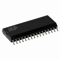
CLRC63201T/0FE,112 NXP Semiconductors, CLRC63201T/0FE,112 Datasheet - Page 30

CLRC63201T/0FE,112
Manufacturer Part Number
CLRC63201T/0FE,112
Description
IC I.CODE HS READER 32-SOIC
Manufacturer
NXP Semiconductors
Series
I-Coder
Specifications of CLRC63201T/0FE,112
Rf Type
Read Only
Frequency
13.56MHz
Features
ISO14443-A, ISO14443-B, ISO15693, ISO18000-3
Package / Case
32-SOIC (0.300", 7.50mm Width)
Product
RFID Readers
Operating Temperature Range
- 25 C to + 85 C
Lead Free Status / RoHS Status
Lead free / RoHS Compliant
Lead Free Status / RoHS Status
Lead free / RoHS Compliant, Lead free / RoHS Compliant
Other names
568-2199-5
935269690112
CLRC632
CLRC63201TD
935269690112
CLRC632
CLRC63201TD
Available stocks
Company
Part Number
Manufacturer
Quantity
Price
Company:
Part Number:
CLRC63201T/0FE,112
Manufacturer:
IR
Quantity:
3 400
Part Number:
CLRC63201T/0FE,112
Manufacturer:
NXP/恩智浦
Quantity:
20 000
NXP Semiconductors
CLRC632_35
Product data sheet
PUBLIC
9.7.3 Initialization phase
9.7.4 Initializing the parallel interface type
9.8 Oscillator circuit
The initialization phase automatically follows the reset phase and takes 128 clock cycles.
During the initializing phase the content of the EEPROM blocks 1 and 2 is copied into the
register subaddresses 10h to 2Fh (see
Remark: During the production test, the CLRC632 is initialized with default configuration
values. This reduces the microprocessor’s configuration time to a minimum.
A different initialization sequence is used for each microprocessor. This enables detection
of the correct microprocessor interface type and synchronization of the microprocessor’s
and the CLRC632’s start-up. See
different connections for each microprocessor interface type.
During StartUp phase, the command value is set to 3Fh once the oscillator attains clock
frequency stability at an amplitude of > 90 % of the nominal 13.56 MHz clock frequency. At
the end of the initialization phase, the CLRC632 automatically switches to idle and the
command value changes to 00h.
To ensure correct detection of the microprocessor interface, the following sequence is
executed:
The clock applied to the CLRC632 acts as a time basis for the synchronous system
encoder and decoder. The stability of the clock frequency is an important factor for correct
operation. To obtain highest performance, clock jitter must be as small as possible. This is
best achieved by using the internal oscillator buffer with the recommended circuitry.
Fig 11. Quartz clock connection
•
•
•
•
the Command register is read until the 6-bit register value is 00h. On reading the 00h
value, the internal initialization phase is complete and the CLRC632 is ready to be
controlled
write 80h to the Page register to initialize the microprocessor interface
read the Command register. If it returns a value of 00h, the microprocessor interface
was successfully initialized
write 00h to the Page registers to activate linear addressing mode.
Rev. 3.5 — 10 November 2009
Multiple protocol contactless reader IC (MIFARE/I-CODE1)
073935
Section 9.1.3 on page 8
15 pF
OSCOUT
CLRC632
Section 9.2.2 on page
13.56 MHz
OSCIN
001aak614
15 pF
for detailed information on the
13).
CLRC632
© NXP B.V. 2009. All rights reserved.
30 of 126


