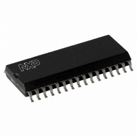
CLRC63201T/0FE,112 NXP Semiconductors, CLRC63201T/0FE,112 Datasheet - Page 39

CLRC63201T/0FE,112
Manufacturer Part Number
CLRC63201T/0FE,112
Description
IC I.CODE HS READER 32-SOIC
Manufacturer
NXP Semiconductors
Series
I-Coder
Specifications of CLRC63201T/0FE,112
Rf Type
Read Only
Frequency
13.56MHz
Features
ISO14443-A, ISO14443-B, ISO15693, ISO18000-3
Package / Case
32-SOIC (0.300", 7.50mm Width)
Product
RFID Readers
Operating Temperature Range
- 25 C to + 85 C
Lead Free Status / RoHS Status
Lead free / RoHS Compliant
Lead Free Status / RoHS Status
Lead free / RoHS Compliant, Lead free / RoHS Compliant
Other names
568-2199-5
935269690112
CLRC632
CLRC63201TD
935269690112
CLRC632
CLRC63201TD
Available stocks
Company
Part Number
Manufacturer
Quantity
Price
Company:
Part Number:
CLRC63201T/0FE,112
Manufacturer:
IR
Quantity:
3 400
Part Number:
CLRC63201T/0FE,112
Manufacturer:
NXP/恩智浦
Quantity:
20 000
NXP Semiconductors
CLRC632_35
Product data sheet
PUBLIC
9.11.2.1 Active antenna concept
Table 30.
See
The TxControl register ModulatorSource[1:0] bits define the signal used to modulate the
transmitted 13.56 MHz energy carrier. The modulated signal drives pins TX1 and TX2.
Table 31.
See
The MFOUTSelect register MFOUTSelect[2:0] bits select the output signal which is to be
routed to pin MFOUT.
Table 32.
See
To use the MFOUTSelect[2:0] bits, the TestDigiSelect register SignalToMFOUT bit must
be logic 0.
The CLRC632 analog and digital circuitry is accessed using pins MFIN and MFOUT.
Table 33
Number
0
1
2
3
Number
0
1
2
3
Number
0
1
2
3
4
5
6
7
Table 96 on page 67
Table 96 on page 67
Table 110 on page 70
lists the required settings.
DecoderSource
[1:0]
00
01
10
11
ModulatorSource
[1:0]
00
01
10
11
MFOUTSelect
[2:0]
000
001
010
011
100
101
110
111
DecoderSource[1:0] values
ModulatorSource[1:0] values
MFOUTSelect[2:0] values
Rev. 3.5 — 10 November 2009
for additional information.
for additional information.
for additional information.
Signal routed to pin MFOUT
constant LOW
constant HIGH
modulation signal (envelope) from the internal encoder
serial data stream to be transmitted; the same as for
MFOUTSelect[2:0] = 001 but not encoded by the selected pulse
encoder
output signal of the receiver circuit; card modulation signal
regenerated and delayed
output signal of the subcarrier demodulator; Manchester coded card
signal
reserved
reserved
Multiple protocol contactless reader IC (MIFARE/I-CODE1)
Input signal to decoder
constant 0
output of the analog part. This is the default configuration
direct connection to pin MFIN; expects an 847.5 kHz subcarrier
signal modulated by a Manchester encoded signal
direct connection to pin MFIN; expects a Manchester encoded
signal
Input signal to modulator
constant 0 (energy carrier off on pins TX1 and TX2)
constant 1 (continuous energy carrier on pins TX1 and TX2)
modulation signal (envelope) from the internal encoder. This is the
default configuration.
direct connection to MFIN; expects a Miller pulse coded signal
073935
CLRC632
© NXP B.V. 2009. All rights reserved.
39 of 126


