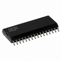
CLRC63201T/0FE,112 NXP Semiconductors, CLRC63201T/0FE,112 Datasheet - Page 36

CLRC63201T/0FE,112
Manufacturer Part Number
CLRC63201T/0FE,112
Description
IC I.CODE HS READER 32-SOIC
Manufacturer
NXP Semiconductors
Series
I-Coder
Specifications of CLRC63201T/0FE,112
Rf Type
Read Only
Frequency
13.56MHz
Features
ISO14443-A, ISO14443-B, ISO15693, ISO18000-3
Package / Case
32-SOIC (0.300", 7.50mm Width)
Product
RFID Readers
Operating Temperature Range
- 25 C to + 85 C
Lead Free Status / RoHS Status
Lead free / RoHS Compliant
Lead Free Status / RoHS Status
Lead free / RoHS Compliant, Lead free / RoHS Compliant
Other names
568-2199-5
935269690112
CLRC632
CLRC63201TD
935269690112
CLRC632
CLRC63201TD
Available stocks
Company
Part Number
Manufacturer
Quantity
Price
Company:
Part Number:
CLRC63201T/0FE,112
Manufacturer:
IR
Quantity:
3 400
Part Number:
CLRC63201T/0FE,112
Manufacturer:
NXP/恩智浦
Quantity:
20 000
NXP Semiconductors
CLRC632_35
Product data sheet
PUBLIC
9.10.2.2 Amplifier
Automatic calibration can be set-up to execute at the end of each Transceive command if
bit ClkQCalib = logic 0. Setting bit ClkQCalib = logic 1 disables all automatic calibrations
except after the reset sequence. Automatic calibration can also be triggered by the
software when bit ClkQCalib has a logic 0 to logic 1 transition.
Remark: The duration of the automatic Q-clock calibration is 65 oscillator periods or
approximately 4.8 s.
The ClockQControl register’s ClkQDelay[4:0] value is proportional to the phase-shift
between the Q-clock and the I-clock. The ClkQ180Deg status flag bit is set when the
phase-shift between the Q-clock and the I-clock is greater than 180 .
Remark:
The demodulated signal must be amplified by the variable amplifier to achieve the best
performance. The gain of the amplifiers can be adjusted using the RxControl1 register
Gain[1:0] bits; see
Table 29.
See
Register setting
00
01
10
11
Fig 13. Automatic Q-clock calibration
•
•
•
The StartUp configuration file enables automatic Q-clock calibration after a reset
If bit ClkQCalib = logic 1, automatic calibration is not performed. Leaving this bit set to
logic 1 can be used to permanently disable automatic calibration.
It is possible to write data to the ClkQDelay[4:0] bits using the microprocessor. The
aim could be to disable automatic calibration and set the delay using the software.
Configuring the delay value using the software requires bit ClkQCalib to have been
previously set to logic 1 and a time interval of at least 4.8 s has elapsed. Each delay
value must be written with bit ClkQCalib set to logic 1. If bit ClkQCalib is logic 0, the
configured delay value is overwritten by the next automatic calibration interval.
Table 86 “RxControl1 register bit descriptions” on page 64
Gain factors for the internal amplifier
Table
Transceive command
from reset sequence
Rev. 3.5 — 10 November 2009
calibration impulse
calibration impulse
29.
from end of
Multiple protocol contactless reader IC (MIFARE/I-CODE1)
073935
ClkQCalib bit
Gain factor [dB]
(simulation results)
20
24
31
35
a rising edge initiates
Q-clock calibration
for additional information.
001aak616
CLRC632
© NXP B.V. 2009. All rights reserved.
36 of 126


