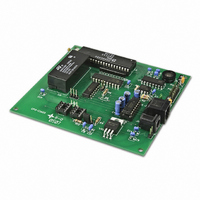
IS-C1603 NKK Switches, IS-C1603 Datasheet - Page 5

IS-C1603
Manufacturer Part Number
IS-C1603
Description
CONTROL FOR 36X24 LCD PB/DISPLAY
Manufacturer
NKK Switches
Datasheet
1.IS-L0251-C.pdf
(45 pages)
Specifications of IS-C1603
Accessory Type
Controller
Description/function
SMARTSWITCH Development Kit
For Use With/related Products
SmartSwitch™ Switches
For Use With
IS01BCEF - SMARTDISPLAY SUPER YEL/GRN LEDIS01BCE - SMARTDISPLAY SUPER YELLOW LEDIS15SBFP4B - SMARTSWITCH COMPACT WHITE LEDIS15SBCP4EF - SMARTSWITCH COMPACT YEL/GRN LEDIS15SACP4CF - SMARTSWITCH COMPACT RED/GRN LEDIS15ABFP4B - SMARTSWITCH STD BLK W/WHITE LEDIS15ABDP4B - SMARTSWITCH STD BLU W/WHITE LEDIS15ABDP4EG - SMARTSWITCH STD YELLOW/BLUE LEDIS15ABDP4E - SMARTSWITCH STD BLUE W/YEL LEDIS15ABCP4EF - SMARTSWITCH STD YEL/GRN LEDIS15ABCP4E - SMARTSWITCH STD LED YELLOWIS15AACP4CF - SMARTSWITCH STD YEL RED/GRN LED360-2334 - SMARTDISPLAY RED/GREEN/BLUE360-2333 - SMARTDISPLAY SUPER RED/GREEN LED360-2332 - SMARTSWITCH STANDARD RED/GRN/BLU360-2331 - SMARTSWITCH COMPACT RED/GRN/BLU360-2330 - SMARTSWITCH STD RED/GRN LED360-2329 - SMARTSWITCH COMPACT RED/GRN LED
Lead Free Status / RoHS Status
Contains lead / RoHS non-compliant
Other names
360-2427
7850 East Gelding Drive • Scottsdale, AZ 85260-3420
Note: Improper installation of the Logic Boards could damage either/both the Logic Boards and
controller.
3. Operational Detail
Power-up Sequence:
Each switch has a Pointer. There are 255 addresses in the memory (01H to FFH). Each Address holds a Page of
data. Each Page has a Legend Block (image data), LCD/LED code, control code, Attribute block, and user-
defined look-up tables.
Upon power-up the data from Page 1 is displayed on switch 1, the data from Page 2 is displayed on switch 2
and so on up to Page 16 which is displayed on switch 16.
The display data for the switches are refreshed from the Page data. The LCD/LED codes are transferred to an
intermediate buffer for refresh. Therefore any command from host that make changes to the images will go to
effect immediately but any command from host that changes the LCD/LED code in a Page will go to effect
immediately only if it also transfers the code to intermediate buffer.
After power-up or reset, the controller transmits 11H. This lets the host know that the controller is on line and
ready for commands.
The controller then waits for a switch action or a command from the host before updating the switches’
displays.
Main Operational Mode:
The controller takes the following actions upon a switch press/release.
1. Switch Release:
A.
B.
C.
D.
E.
IS-C1603 Intelligent Controller Users Manual C.doc
1.
2.
or until there is a null character in HEX format from user-defined switch release look-up table
associated with the switch number.
value of the image being displayed.
until there is a null character in HEX format from user-defined image release look-up table associated
with the Pointer.
do the following:
If bit 0 of FLAG-A is enabled (default: enabled), transmit (Switch # + B0H) to host in HEX format.
If bit 2 of FLAG-C is enabled (default: disabled), transmit to host up to a maximum of 16 characters
If bit 0 of FLAG-C is enabled (default: disabled), transmit to host in ASCII HEX format the Pointer
If bit 1 of FLAG-C is enabled (default: disabled), transmit to host up to a maximum of 8 characters or
If bit 5 of FLAG-A is enabled (default: enabled) and bit 2 of FLAG-B is equal to one (default: 0) then
zero, then increase or decrease the brightness accordingly.
Image. If any of the Addresses in the attribute block is equal to zero do not change that Pointer.
Use current Pointer to find the associated Address, if the viewing angle/ brightness code is not
Update the Pointers with the Addresses from the Attribute Block in the Page of the displaying
Toll Free 1.877.2BUYNKK (877.228.9655) • Phone 480.991.0942 • Fax 480.998.1435
IS-C1603 Intelligent Controller Users
www.nkkswitches.com • Email engineering@nkkswitches.com
Manual
Page 5 of 45
0110


