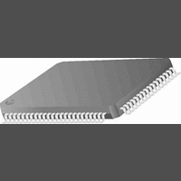
CR16MCS9VJE8 National Semiconductor, CR16MCS9VJE8 Datasheet - Page 153

CR16MCS9VJE8
Manufacturer Part Number
CR16MCS9VJE8
Description
16-Bit Microcontroller IC
Manufacturer
National Semiconductor
Datasheet
1.CR16MCS9VJE8.pdf
(156 pages)
Specifications of CR16MCS9VJE8
Controller Family/series
CR16X
Core Size
16 Bit
Program Memory Size
64K X 8 Flash
Digital Ic Case Style
PQFP
No. Of Pins
80
Mounting Type
Surface Mount
Clock Frequency
25MHz
Lead Free Status / RoHS Status
Contains lead / RoHS non-compliant
Available stocks
Company
Part Number
Manufacturer
Quantity
Price
Company:
Part Number:
CR16MCS9VJE8
Manufacturer:
ON
Quantity:
8 917
Company:
Part Number:
CR16MCS9VJE8-CBB
Manufacturer:
ON
Quantity:
846
Company:
Part Number:
CR16MCS9VJE8-CBC
Manufacturer:
ON
Quantity:
109
Company:
Part Number:
CR16MCS9VJE8-CBD
Manufacturer:
ON
Quantity:
17
Company:
Part Number:
CR16MCS9VJE8-CBE
Manufacturer:
ON
Quantity:
1 950
26.1.3
Reset receive buffer tags before transmitting a message
The receive tag of a CAN receive buffer is reset when the
CPU updates the buffer status in the CNSTAT.ST-field to any
value which disables the receive buffer. Therefore the user
should write the sequence RX_NOT_ACTIVE - RX_READY
to all receive buffers which have an identifier filter matching
the identifier of the frame to be sent next before the message
is sent.
Modified CAN Communication Sequence:
The same CAN buffer settings as described in also apply to
this example.
Advantage:
No receive buffer is overwritten by a message sent by the
same CR16CAN node.
Disadvantage:
The corresponding receive buffers must be disabled for a
short period of time. During this time, when the receive buff-
ers are in the RX_NOT_ACTIVE state, correct incoming
messages from other CAN nodes will get lost.
This method is more suitable compared to the method de-
scribed in Section, if the number of transmit buffers with
identifier ID_RX_TX is lower than the number of receive buff-
ers set up with the corresponding identifier mask.
Reset receive buffer tags after reception of a message
The receive tag of a CAN receive buffer is reset when the
CPU updates the buffer status in the CNSTAT.ST-field to any
value which disables the receive buffer. Therefore the user
(BUFFLOCK disabled)
1. Message sent from another CAN node received into
2. Message sent from another CAN node received into
3. CAN buffer 0 sends a frame (status set to TX_ONCE).
4. Status of CAN buffer 1 and 2 remains RX_READY, be-
1. Message sent from another CAN node received into
2. CPU reads out data from CAN buffer 1 and resets the
3. Write RX_NOT_ACTIVE to CNSTAT.ST-field of buffer 1
4. Write RX_READY to CNSTAT.ST-field of buffer 1 and
5. CAN buffer 0 sends a frame (status set to TX_ONCE).
6. Status of CAN buffer 1 remains RX_READY, because it
buffer 1.
Buffer 1 and buffer 2 are tagged for reception of this
message.
buffer 3 (ID=0x15555003).
Only buffer 3 is now tagged for reception.
cause they have not received the message sent by buff-
er 0.
buffer 1.
Buffer 1 and buffer 2 are tagged for reception of this
message.
buffer state from RX_FULL to RX_READY.
and buffer 2.
Buffer 1 and buffer 2 are NOT tagged for reception any-
more.
buffer 2.
has NOT received the message sent by buffer 0.
CR16CAN Problem Solutions
153
should write the sequence RX_NOT_ACTIVE - RX_READY
to this receive buffer, which has received the latest message.
Modified CAN Communication Sequence:
In the CAN communication example described below, the
buffer 14 is set up as basic CAN path, which is able to receive
all standard frames. The buffers 1 to 13 cannot receive the
frame sent by buffer 0.
Advantage:
No receive buffer is overwritten by a message sent by the
same CR16CAN node.
Disadvantage:
The corresponding receive buffers must be disabled for a
short period of time. During this time, when the receive buff-
ers are in the RX_NOT_ACTIVE state, correctly incoming
messages from other CAN nodes will get lost.
This method is more suitable compared to the method de-
scribed in Section, if the number of transmit buffers with
identifier ID_RX_TX is higher than the number of receive
buffers set up with the corresponding identifier mask. This is
the case if only the basic CAN path to buffer 14 is configured
to receive a range of identifiers, including the identifier
ID_RX_TX. All other buffers are configured with unique iden-
tifier filters.
Receive all frames and discard those, which were sent
by the same CR16CAN node.
Another approach to overcome this problem uses the Time
Stamp counter of the CR16CAN module to determine,
whether a message was sent and received at the same time.
This is the case when a transmitted frame is received by the
same CAN node.
1. Message sent from another CAN node received into
2. CPU reads out data from CAN buffer 14.
3. Write RX_NOT_ACTIVE to CNSTAT.ST-field of buffer
4. Write RX_READY to CNSTAT.ST-field of buffer 14.
5. CAN buffer 0 sends a frame (status set to TX_ONCE).
6. Status of CAN buffer 14 remains RX_READY, because
CAN Buffer
Filter Masks:
BMSKB = 0xFFF0
BMSKX = 0x0000
Buffer configuration
Number
buffer 14.
Buffer 14 is tagged for reception of this message.
14.
Buffer 14 is NOT tagged for reception anymore.
it has NOT received the message sent by buffer 0.
14
0
CAN Buffer Status
TX_NOT_ACTIVE
RX_READY
:
any standard frame
Buffer Identifier
ID1.IDE bit = 1
www.national.com


