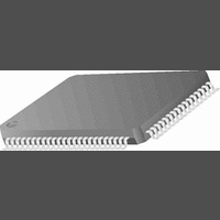
CR16MCS9VJE8 National Semiconductor, CR16MCS9VJE8 Datasheet - Page 93

CR16MCS9VJE8
Manufacturer Part Number
CR16MCS9VJE8
Description
16-Bit Microcontroller IC
Manufacturer
National Semiconductor
Datasheet
1.CR16MCS9VJE8.pdf
(156 pages)
Specifications of CR16MCS9VJE8
Controller Family/series
CR16X
Core Size
16 Bit
Program Memory Size
64K X 8 Flash
Digital Ic Case Style
PQFP
No. Of Pins
80
Mounting Type
Surface Mount
Clock Frequency
25MHz
Lead Free Status / RoHS Status
Contains lead / RoHS non-compliant
Available stocks
Company
Part Number
Manufacturer
Quantity
Price
Company:
Part Number:
CR16MCS9VJE8
Manufacturer:
ON
Quantity:
8 917
Company:
Part Number:
CR16MCS9VJE8-CBB
Manufacturer:
ON
Quantity:
846
Company:
Part Number:
CR16MCS9VJE8-CBC
Manufacturer:
ON
Quantity:
109
Company:
Part Number:
CR16MCS9VJE8-CBD
Manufacturer:
ON
Quantity:
17
Company:
Part Number:
CR16MCS9VJE8-CBE
Manufacturer:
ON
Quantity:
1 950
Special error handling for the TEC counter is performed in
the following situations:
Receive Error Counter Conditions
A receiver detects a Bit Error during sending an active error flag.
A receiver detects a ‘dominant’ bit as the first bit after sending an error flag
After detecting the 14th consecutive ‘dominant’ bit following an active error flag or overload
flag, or after detecting the 8th consecutive ‘dominant’ bit following a passive error flag.
After each sequence of additional 8 consecutive ‘dominant’ bits.
Any other error condition (stuff, frame, CRC, ACK)
A valid reception or transmission
Transmit Error Counter Conditions
A transmitter detects a Bit Error during sending an active error flag
After detecting the 14th consecutive ‘dominant’ bit following an active error flag or overload flag
or after detecting the 8th consecutive ‘dominant’ bit following a passive error flag.
After each sequence of additional 8 consecutive ‘dominant’ bits.
Any other error condition (stuff, frame, CRC, ACK)
A valid reception or transmission
— Synchronize
— Error active
— Error Warning
— Error passive
— A stuff error occurs during arbitration, when a transmit-
a. This table provides an overview of the CAN error conditions and the behavior of the CR16CAN; for a detailed
b. If the MSB (bit 7) of the REC is set, the node is error passive and the REC will not increment any further.
Once the CR16CAN is enabled, it goes into a synchro-
nization state to synchronize with the bus by waiting for
11 consecutive recessive bits. After that the CR16CAN
becomes error active and can participate in the bus
communication. This state must also be entered after
waking-up the device via the Multi-Input Wake-Up fea-
ture. See System Start-Up and Multi-Input Wake-Up
on page 116.
An error active unit can participate in bus communica-
tion and may send an active (‘dominant’) error flag.
The Error Warning state is a sub-state of Error Active
to indicate a heavily disturbed bus. The CR16CAN be-
haves as in Error Active mode. The device is reset into
the Error Active mode if the value of both counters is
less than 96.
An error passive unit can participate in bus communi-
cation. However, if the unit detects an error it is not al-
lowed to send an active error flag. The unit sends only
a passive (‘recessive’) error flag. A device is error pas-
sive when the transmit error counter or the receive er-
ror counter is greater than 127. A device becoming
ted ‘recessive’ stuff bit is received as a ‘dominant’ bit.
This does not lead to an increment of the TEC.
description of the error management and fault confinement rules, please refer to the CAN Specification 2.0B
b
Condition
Table 20 Error Counter Handling
a
93
Error Counters
The CR16CAN module contains two error counters to per-
form the error management. The receive error counter (REC)
and the transmit error counter (TEC) are 8-bits wide, located
in the 16-bit wide CANEC register. The counters are modified
by the CR16CAN according to the rules listed in Table20 “Er-
ror Counter Handling”.
The Error counters can be read by the users software as de-
scribed under CAN Error Counter Register (CANEC) on
page 115.
— Bus off
— An ACK-error occurs in an error passive device and no
error passive will send an active error flag. An error
passive device becomes error active again when both
transmit and receive error counter are less than 128.
A unit that is bus off has the output drivers disabled,
i.e., it does not participate in any bus activity. A device
is bus off when the transmit error counter is greater
than 255. A bus off device will become error active
again after monitoring 128*11 ‘recessive’ bits (includ-
ing bus idle) on the bus. When the device goes from
‘bus off’ to ‘error active’, both error counters will have
the value ‘0’.
‘dominant’ bits are detected while sending the passive
error flag. This does not lead to an increment of the
TEC.
increment by 8
increment by 8
increment by 8
increment by 1
decrement by 1 unless
counter is already 0
increment by 8
increment by 8
increment by 8
decrement by 1 unless
counter is already 0
Action
www.national.com


