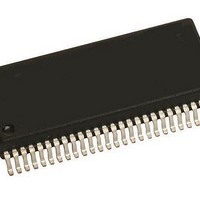
MM908E625ACDWB Freescale Semiconductor, MM908E625ACDWB Datasheet - Page 31

MM908E625ACDWB
Manufacturer Part Number
MM908E625ACDWB
Description
IC QUAD HALF BRDG MCU/LIN 54SOIC
Manufacturer
Freescale Semiconductor
Datasheets
1.MM908E625.pdf
(48 pages)
2.MM908E625ACDWB.pdf
(48 pages)
3.MM908E625ACDWB.pdf
(48 pages)
4.MM908E625ACDWB.pdf
(48 pages)
5.MM908E625ACDWB.pdf
(40 pages)
Specifications of MM908E625ACDWB
Applications
Automotive Mirror Control
Core Processor
HC08
Program Memory Type
FLASH (16 kB)
Controller Series
908E
Ram Size
512 x 8
Interface
SCI, SPI
Number Of I /o
13
Voltage - Supply
8 V ~ 18 V
Operating Temperature
-40°C ~ 85°C
Mounting Type
Surface Mount
Package / Case
54-SOIC (0.300", 7.50mm Width) Exposed Pad
Program Memory Size
16 KB
Number Of Programmable I/os
54
Number Of Timers
16
Operating Supply Voltage
- 18 V to + 28 V
Maximum Operating Temperature
+ 85 C
Mounting Style
SMD/SMT
Minimum Operating Temperature
- 40 C
Lead Free Status / RoHS Status
Contains lead / RoHS non-compliant
Available stocks
Company
Part Number
Manufacturer
Quantity
Price
Company:
Part Number:
MM908E625ACDWB
Manufacturer:
FREESCALE Semiconductor
Quantity:
26
HALL-EFFECT SENSOR INPUT PIN STATUS
REGISTER (HASTAT)
effect sensor input pin Hx is enabled (HxEN = 1). Reset
clears the H3F:H1F bits.
HALF-BRIDGE CONTROL
general enable of the circuitry is done by setting PSON in the
System Control Register (SYSCTL). HBx_L and HBx_H form
one half-bridge. It is not possible to switch on both MOSFETs
in one half-bridge at the same time. If both bits are set, the
high-side MOSFET has a higher priority.
Hall-Effect Sensor Input Pin Flag Bits (H3F:H1F)
Analog Integrated Circuit Device Data
Freescale Semiconductor
Reset
Write
Read
Bits
These read-only flag bits reflect the input Hx while the Hall-
• 1 = Hall-effect sensor input pin current above threshold
Each output MOSFET can be controlled individually. The
Register Name and Address: HASTAT - $09
7
0
0
6
0
0
Control
5
0
0
4
0
0
3
0
0
Figure 17. Half-Bridge Push-Pull Output Driver
Current
On/Off
On/Off
Status
BEMF
Status
Limit
H3F
2
0
H2F
1
0
Overtemperature Protection,
Overcurrent Protection
Overcurrent Protection
High-Side Driver
Low-Side Driver
H1F
Current Limitation,
Current Recopy,
0
0
Charge Pump,
HALF-BRIDGES
output stages. The half-bridges can be used in H-Bridge,
high-side, or low-side configurations.
(HBOUT) owing to the fact that all half-bridge outputs are
switched off.
half-bridge being on at the same time, a break-before-make
circuit exists. Switching the high-side MOSFET on is inhibited
as long as the potential between gate and V
certain threshold. Switching the low-side MOSFET on is
blocked as long as the potential between gate and source of
the high-side MOSFET did not fall below a certain threshold.
• 0 = Hall-effect sensor input pin current below threshold
Outputs HB1:HB4 provide four low-resistive half-bridge
Reset clears all bits in the H-Bridge Output Register
HB1:HB4 output features:
• Short circuit (overcurrent) protection on high-side and
• Current recopy feature (low side MOSFET)
• Overtemperature protection
• Overvoltage and undervoltage protection
• Current limitation feature (low side MOSFET)
To avoid both MOSFETs (high side and low side) of one
low-side MOSFETs
LOGIC COMMANDS AND REGISTERS
FUNCTIONAL DEVICE OPERATION
VSUP
GND
SS
is not below a
908E625
HBx
31


