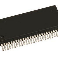
MM908E625ACDWB Freescale Semiconductor, MM908E625ACDWB Datasheet - Page 47

MM908E625ACDWB
Manufacturer Part Number
MM908E625ACDWB
Description
IC QUAD HALF BRDG MCU/LIN 54SOIC
Manufacturer
Freescale Semiconductor
Datasheets
1.MM908E625.pdf
(48 pages)
2.MM908E625ACDWB.pdf
(48 pages)
3.MM908E625ACDWB.pdf
(48 pages)
4.MM908E625ACDWB.pdf
(48 pages)
5.MM908E625ACDWB.pdf
(40 pages)
Specifications of MM908E625ACDWB
Applications
Automotive Mirror Control
Core Processor
HC08
Program Memory Type
FLASH (16 kB)
Controller Series
908E
Ram Size
512 x 8
Interface
SCI, SPI
Number Of I /o
13
Voltage - Supply
8 V ~ 18 V
Operating Temperature
-40°C ~ 85°C
Mounting Type
Surface Mount
Package / Case
54-SOIC (0.300", 7.50mm Width) Exposed Pad
Program Memory Size
16 KB
Number Of Programmable I/os
54
Number Of Timers
16
Operating Supply Voltage
- 18 V to + 28 V
Maximum Operating Temperature
+ 85 C
Mounting Style
SMD/SMT
Minimum Operating Temperature
- 40 C
Lead Free Status / RoHS Status
Contains lead / RoHS non-compliant
Available stocks
Company
Part Number
Manufacturer
Quantity
Price
Company:
Part Number:
MM908E625ACDWB
Manufacturer:
FREESCALE Semiconductor
Quantity:
26
Device on Thermal Test Board
Analog Integrated Circuit Device Data
Freescale Semiconductor
Material:
Outline:
Area A:
Ambient Conditions:
PTD0/TACH0/BEMF
PTB7/AD7/TBCH1
PTB6/AD6/TBCH0
PTD1/TACH1
PTC2/MCLK
PTC4/OSC1
PTC3/OSC2
PTB5/AD5
PTB4/AD4
PTB3/AD3
PTB1/AD1
VSUP1
VSUP2
RST_A
FGEN
BEMF
IRQ_A
GND1
HB1
HB2
RST
IRQ
LIN
NC
NC
NC
SS
10.3 mm x 5.1 mm Exposed Pad
908E625 Pin Connections
17.9 mm x 7.5 mm Body
1
2
3
4
5
6
7
8
9
10
11
12
13
14
15
16
17
18
19
20
21
22
23
24
25
26
27
54-Pin SOICW-EP
0.65 mm Pitch
Single layer printed circuit board
FR4, 1.6 mm thickness
Cu traces, 0.07 mm thickness
80 mm x 100 mm board area,
including edge connector for thermal
testing
Cu heat-spreading areas on board
surface
Natural convection, still air
Exposed
Pad
54
53
52
51
50
49
48
47
46
45
44
43
42
41
40
39
38
37
36
35
34
33
32
31
30
29
28
PTA0/KBD0
PTA1/KBD1
PTA2/KBD2
FLSVPP
PTA3/KBD3
PTA4/KBD4
VREFH
VDDA
EVDD
EVSS
VSSA
VREFL
PTE1/RXD
RXD
VSS
PA1
VDD
H1
H2
H3
HVDD
NC
HB4
VSUP3
GND2
HB3
HS
Figure 28. Thermal Test Board
Table 15. Thermal Resistance Performance
ambient air.
the reference location on the board surface near a center
lead of the package.
die that is heated. Index n refers to the number of the die
where the junction temperature is sensed.
Resistance
R
R
Thermal
R
R
This device is a dual die package. Index m indicates the
θ
θ
JA mn
JS mn
θ JA
θ JSmn
is the thermal resistance between die junction and
is the thermal resistance between die junction and
Area A
(mm
300
600
300
600
0
0
2
)
A
A
1 = Power Chip, 2 = Logic Chip
m = 1,
n = 1
53
39
35
21
15
14
THERMAL ADDENDUM (REV 2.0)
ADDITIONAL DOCUMENTATION
m = 1, n = 2
m = 2, n = 1
9.0
48
34
30
16
11
m = 2,
n = 2
908E625
(°C/W)
53
38
34
20
15
13
47


