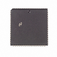
DP83901AV National Semiconductor, DP83901AV Datasheet - Page 15

DP83901AV
Manufacturer Part Number
DP83901AV
Description
IC CONTROLLR SER NETWK IN 68PLCC
Manufacturer
National Semiconductor
Datasheet
1.DP83901AV.pdf
(62 pages)
Specifications of DP83901AV
Controller Type
Serial Network Interface Controller
Interface
Serial
Voltage - Supply
5V
Current - Supply
110mA
Mounting Type
Surface Mount
Package / Case
68-LCC (J-Lead)
Lead Free Status / RoHS Status
Contains lead / RoHS non-compliant
Operating Temperature
-
Other names
*DP83901AV
Available stocks
Company
Part Number
Manufacturer
Quantity
Price
Company:
Part Number:
DP83901AV
Manufacturer:
NS
Quantity:
5 510
Part Number:
DP83901AV
Manufacturer:
NS/国半
Quantity:
20 000
7 0 Packet Reception
Enabling the SNIC On An Active Network
After the SNIC has been initialized the procedure for dis-
abling and then re-enabling the SNIC on the network is simi-
lar to handling Receive Buffer Ring overflow as described
previously
1 Program Command Register for page 0 (Command
2 Initialize Data Configuration Register (DCR)
3 Clear Remote Byte Count Registers (RBCR0 RBCR1)
4 Initialize Receive Configuration Register (RCR)
5 Place the SNIC in LOOPBACK mode 1 or 2 (Transmit
6 Initialize Receive Buffer Ring
7 Clear Interrupt Status Register (ISR) by writing 0FFH to
8 Initialize Interrupt Mask Register (IMR)
9 Program Command Register for page 1 (Command
Register
Configuration Register
(BNDRY)
(PSTOP)
it
Register
i) Initialize Physical Address Registers (PAR0–PAR5)
ii) Initialize Multicast Address Registers (MAR0 – MAR7)
iii) Initialize CURRent pointer
e
e
Page Start (PSTART)
21H)
61H)
e
02H or 04H)
Termination of Received Packet Packet Accepted
(Continued)
Boundary Pointer
and Page Stop
15
10) Put SNIC in START mode (Command Register
11) Initialize the Transmit Configuration for the intended val-
END OF PACKET OPERATIONS
At the end of the packet the SNIC determines whether the
received packet is to be accepted or rejected It either
branches to a routine to store the Buffer Header or to anoth-
er routine that recovers the buffers used to store the packet
SUCCESSFUL RECEPTION
If the packet is successfully received the DMA is restored
to the first buffer used to store the packet (pointed to by the
Current Page Register) The DMA then stores the Receive
Status a Pointer to where the next packet will be stored
(Buffer 4) and the number of received bytes Note that the
remaining bytes in the last buffer are discarded and recep-
tion of the next packet begins on the next empty 256-byte
buffer boundary The Current Page Register is then initial-
ized to the next available buffer in the Buffer Ring (The
location of the next buffer had been previously calculated
and temporarily stored in an internal scratchpad register )
The local receive DMA is still not active since the SNIC
is in LOOPBACK
ue The SNIC is now ready for transmission and recep-
tion
TL F 10469– 12
e
22H)


