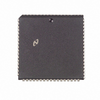
DP83901AV National Semiconductor, DP83901AV Datasheet - Page 6

DP83901AV
Manufacturer Part Number
DP83901AV
Description
IC CONTROLLR SER NETWK IN 68PLCC
Manufacturer
National Semiconductor
Datasheet
1.DP83901AV.pdf
(62 pages)
Specifications of DP83901AV
Controller Type
Serial Network Interface Controller
Interface
Serial
Voltage - Supply
5V
Current - Supply
110mA
Mounting Type
Surface Mount
Package / Case
68-LCC (J-Lead)
Lead Free Status / RoHS Status
Contains lead / RoHS non-compliant
Operating Temperature
-
Other names
*DP83901AV
Available stocks
Company
Part Number
Manufacturer
Quantity
Price
Company:
Part Number:
DP83901AV
Manufacturer:
NS
Quantity:
5 510
Part Number:
DP83901AV
Manufacturer:
NS/国半
Quantity:
20 000
4 0 Functional Description
ENCODER DECODER (ENDEC) MODULE
The ENDEC consists of four main logical blocks
a) The Manchester encoder accepts NRZ data from the
b) The Manchester decoder receives Manchester data from
c) The collision translator indicates to the controller the
MANCHESTER ENCODER AND DIFFERENTIAL DRIVER
The differential transmit pair on the secondary of the em-
ployed transformer drives up to 50 meters of twisted pair
AUI cable These outputs are source followers which require
two 270
The DP83901A allows both half-step and full-step to be
compatible with Ethernet and IEEE 802 3 With the SEL pin
low (for Ethernet I) Transmit
Transmit
Transmit
provides zero differential voltage to operate with transform-
er coupled loads
MANCHESTER DECODER
The decoder consists of a differential receiver and a PLL to
separate a Manchester decoded data stream into internal
clock signals and data The differential input must be exter-
nally terminated with two 39
if the standard 78
Ethernet applications these resistors are optional To pre-
vent noise from falsely triggering the decoder a squelch
circuit at the input rejects signals with levels less than
duration greater than 30 ns are decoded Data becomes
valid typically within 5 bit times The DP83901A may tolerate
bit jitter up to 18 ns in the received data The decoder de-
tects the end of a frame when no more mid-bit transitions
are detected
COLLISION TRANSLATOR
When the Ethernet transceiver (DP8392 CTI) detects a colli-
sion it generates a 10 MHz signal to the differential collision
inputs (CD
tected active the DP83901A uses this signal to back off its
current transmission and reschedule another one
The collision differential inputs are terminated the same way
as the differential receive inputs The squelch circuitry is
also similar rejecting pulses with levels less than
b
175 mV Signals more negative than
controller encodes the data to Manchester and trans-
mits it differentially to the transceiver through the differ-
ential transmit driver
the transceiver converts it to NRZ data and clock pulses
and sends it to the controller
presence of a valid 10 MHz collision signal to the PLL
b
a
pull-down resistors to ground
g
and Transmit
during idle with SEL high (for IEEE 802 3)
) of the DP83901A When these inputs are de-
transceiver drop cable is used in thin
b
are equal in the idle state This
a
resistors connected in series
is positive with respect to
b
300 mV and a
(Refer to Figure 1 )
b
175 mV
6
NIC (Media Access Control) MODULE
RECEIVE DESERIALIZER
The Receive Deserializer is activated when the input signal
Carrier Sense is asserted to allow incoming bits to be shift-
ed into the shift register by the receive clock The serial
receive data is also routed to the CRC generator checker
The Receive Deserializer includes a synch detector which
detects the SFD (Start of Frame Delimiter) to establish
where byte boundaries within the serial bit stream are locat-
ed After every eight receive clocks the byte wide data is
transferred to the 16-byte FIFO and the Receive Byte Count
is incremented The first six bytes after the SFD are
checked for valid comparison by the Address Recognition
Logic If the Address Recognition Logic does not recognize
the packet the FIFO is cleared
CRC GENERATOR CHECKER
During transmission the CRC logic generates a local CRC
field for the transmitted bit sequence The CRC encodes all
fields after the SFD The CRC is shifted out MSB first follow-
ing the last transmit byte During reception the CRC logic
generates a CRC field from the incoming packet This local
CRC is serially compared to the incoming CRC appended to
the end of the packet by the transmitting node If the local
and received CRC match a specific pattern will be generat-
ed and decoded to indicate no data errors Transmission
errors result in different pattern and are detected resulting
in rejection of a packet (if so programmed)
TRANSMIT SERIALIZER
The Transmit Serializer reads parallel data from the FIFO
and serializes it for transmission The serializer is clocked by
the transmit clock generated internally The serial data is
also shifted into the CRC generator checker At the begin-
ning of each transmission the Preamble and Synch Gener-
ator append 62 bits of 1 0 preamble and a 1 1 synch pat-
tern After the last data byte of the packet has been serial-
ized the 32-bit FCS field is shifted directly out of the CRC
generator In the event of a collision the Preamble and
Synch generator is used to generate a 32-bit JAM pattern of
all 1’s
ADDRESS RECOGNITION LOGIC
The address recognition logic compares the Destination Ad-
dress Field (first 6 bytes of the received packet) to the Phys-
ical address registers stored in the Address Register Array
If any one of the six bytes does not match the pre-pro-
grammed physical address the Protocol Control Logic re-
jects the packet All multicast destination addresses are fil-
tered using a hashing technique (See register description )
If the multicast address indexes a bit that has been set in
the filter bit array of the Multicast Address Register Array
the packet is accepted otherwise it is rejected by the Proto-


