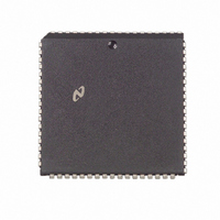
DP83901AV National Semiconductor, DP83901AV Datasheet - Page 34

DP83901AV
Manufacturer Part Number
DP83901AV
Description
IC CONTROLLR SER NETWK IN 68PLCC
Manufacturer
National Semiconductor
Datasheet
1.DP83901AV.pdf
(62 pages)
Specifications of DP83901AV
Controller Type
Serial Network Interface Controller
Interface
Serial
Voltage - Supply
5V
Current - Supply
110mA
Mounting Type
Surface Mount
Package / Case
68-LCC (J-Lead)
Lead Free Status / RoHS Status
Contains lead / RoHS non-compliant
Operating Temperature
-
Other names
*DP83901AV
Available stocks
Company
Part Number
Manufacturer
Quantity
Price
Company:
Part Number:
DP83901AV
Manufacturer:
NS
Quantity:
5 510
Part Number:
DP83901AV
Manufacturer:
NS/国半
Quantity:
20 000
12 0 Loopback Diagnostics
To initiate a loopback the user first assembles the loopback
packet then selects the type of loopback using the Transmit
Configuration register bits LB0 LB1 The transmit configura-
tion register must also be set to enable or disable CRC gen-
eration during transmission The user then issues a normal
transmit command to send the packet During loopback the
receiver checks for an address match and if CRC bit in the
TCR is set the receiver will also check the CRC The last 8
bytes of the loopback packet are buffered and can read out
of the FIFO using FIFO read port
Loopback Modes
MODE 1 Loopback through the NIC Module (LB1
LB0
izer is connected to the deserializer
MODE 2 Loopback through the ENDEC Module (LB1
LB0
SNI the SNIC provides a control (LPBK) that forces the
ENDEC module to loopback all signals
MODE 3 Loopback to Coax (LB1
can be transmitted to the coax in loopback mode to check
all of the transmit and receive paths and the coax itself
Note Collision and Carrier Sense can be generated by the ENDEC module
Note The FIFO may only be read during Loopback Reading the FIFO at
Reading the Loopback Packet
The last 8 bytes of a received packet can be examined by 8
consecutive reads of the FIFO register The FIFO pointer is
incremented after the rising edge of the CPU’s read strobe
by internally synchronizing and advancing the pointer This
may take up to four bus clock cycles if the pointer has not
been incremented by the time the CPU reads the FIFO reg-
ister again the SNIC will insert wait states
Note The FIFO may only be read during Loopback Reading the FIFO at
Alignment of the Received Packet in the FIFO
Reception of the packet in the FIFO begins at location zero
after the FIFO pointer reaches the last location in the FIFO
the pointer wraps to the top of the FIFO overwriting the
previously received data This process continued until the
last byte is received The SNIC then appends the received
byte count in the next two locations of the FIFO The con-
tents of the Upper Byte Count are also copied to the next
FIFO location The number of bytes used in the loopback
packet determined the alignment of the packet in the FIFO
e
e
and are masked by the NIC module It is not possible to go directly
between the loopback modes it is necessary to return to normal oper-
ation (00H) when changing modes
any other time will cause the SNIC to malfunction
any other time will cause the SNIC to malfunction
1) If this loopback is used the NIC Modules’s serial-
0) If the loopback is to be performed through the
e
1 LB0
e
(Continued)
1) Packets
e
e
0
1
34
The alignment for a 64-byte packet is shown below
For the following alignment in the FIFO the packet length
should be (N x 8)
TCR is set CRC will not be appended by the transmitter If
the CRC is appended by the transmitter the 1st four bytes
bytes N-3 to N correspond to the CRC
LOOPBACK TESTS
Loopback capabilities are provided to allow certain tests to
be performed to validate operation of the DP83901A SNIC
prior to transmitting and receiving packets on a live network
Typically these tests may be performed during power up of
a node The diagnostic provides support to verify the follow-
ing
1 Verify integrity of data path Received data is checked
2 Verify CRC logic’s capability to generate good CRC on
Location
Location
against transmitted data
transmit verify CRC on receive (good or bad CRC)
FIFO
FIFO
0
1
2
3
4
5
6
7
0
1
2
3
4
5
6
7
Lower Byte Count
Upper Byte Count
Upper Byte Count
Lower Byte Count
Upper Byte Count
Upper Byte Count
Byte N-3 (CRC1)
Byte N-2 (CRC2)
Byte N-1 (CRC3)
Byte N (CRC4)
Contents
Contents
Last Byte
Byte N-4
a
CRC1
CRC2
CRC3
CRC4
FIFO
FIFO
5 Bytes Note that if the CRC bit in the
Second Byte Read
Second Byte Read
First Byte Read
Last Byte Read
First Byte Read
Last Byte Read


