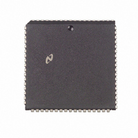
DP83901AV National Semiconductor, DP83901AV Datasheet - Page 7

DP83901AV
Manufacturer Part Number
DP83901AV
Description
IC CONTROLLR SER NETWK IN 68PLCC
Manufacturer
National Semiconductor
Datasheet
1.DP83901AV.pdf
(62 pages)
Specifications of DP83901AV
Controller Type
Serial Network Interface Controller
Interface
Serial
Voltage - Supply
5V
Current - Supply
110mA
Mounting Type
Surface Mount
Package / Case
68-LCC (J-Lead)
Lead Free Status / RoHS Status
Contains lead / RoHS non-compliant
Operating Temperature
-
Other names
*DP83901AV
Available stocks
Company
Part Number
Manufacturer
Quantity
Price
Company:
Part Number:
DP83901AV
Manufacturer:
NS
Quantity:
5 510
Part Number:
DP83901AV
Manufacturer:
NS/国半
Quantity:
20 000
4 0 Functional Description
col Control Logic Each destination address is also checked
for all 1’s which is the reserved broadcast address
FIFO AND BUS OPERATIONS
Overview
To accommodate the different rates at which data comes
from (or goes to) the network and goes to (or comes from)
the system memory the SNIC contains a 16-byte FIFO for
buffering data between the media The FIFO threshold is
programmable allowing filling (or emptying) the FIFO at dif-
ferent rates When the FIFO has filled to its programmed
threshold the local DMA channel transfers these bytes (or
words) into local memory It is crucial that the local DMA is
given access to the bus within a minimum bus latency time
otherwise a FIFO underrun (or overrun) occurs
FIFO underruns or overruns are caused by two conditions
(1) the bus latency is so long that the FIFO has filled (or
emptied) from the network before the local DMA has serv-
iced the FIFO and (2) the bus latency has slowed the
throughput of the local DMA to point where it is slower than
the network data rate (10 Mbit sec) This second condition
is also dependent upon DMA clock and word width (byte
wide or word wide) The worst case condition ultimately lim-
its the overall bus latency which the SNIC can tolerate
Beginning of Receive
At the beginning or reception the SNIC stores entire Ad-
dress field of each incoming packet in the FIFO to deter-
mine whether the packet matches its Physical Address Reg-
isters or maps to one of its Multicast Registers This causes
the FIFO to accumulate 8 bytes Furthermore there are
some synchronization delays in the DMA PLA Thus the
actual time that BREQ is asserted from the time the Start of
Frame Delimiter (SFD) is detected is 7 8 s This operation
affects the bus latencies at 2 and 4-byte thresholds during
the first receive BREQ since the FIFO must be filled to
8 bytes (or 4 words) before issuing a BREQ
End of Receive
When the end of a packet is detected by the ENDEC mod-
ule the SNIC enters its end of packet processing sequence
emptying its FIFO and writing the status information at the
beginning of the packet The SNIC holds onto the bus for
the entire sequence The longest time BREQ may be ex-
tended occurs when a packet ends just as the SNIC per-
forms its last FIFO burst The SNIC in this case performs a
programmed burst transfer followed by flushing the remain-
ing bytes in the FIFO and completed by writing the header
information to memory The following steps occur during
this sequence
1 SNIC issues BREQ because the FIFO threshold has been
reached
(Continued)
7
2 During the burst packet ends resulting in BREQ extend-
3 SNIC flushes remaining bytes from FIFO
4 SNIC performs internal processing to prepare for writing
5 SNIC writes 4-byte (2-word) header
6 SNIC de-asserts BREQ
FIFO Threshold Detection
To assure that no overwriting of data in the FIFO the FIFO
logic flags a FIFO overrun as the 13th byte is written into the
FIFO effectively shortening the FIFO to 13 bytes The FIFO
logic also operates differently in Byte Mode and in Word
Mode In Byte Mode a threshold is indicated when the n
byte has entered the FIFO thus with an 8-byte threshold
the SNIC issues Bus Request (BREQ) when the 9th byte
has entered the FIFO For Word Mode BREQ is not gener-
ated until the n
a 4 word threshold (equivalent to 8-byte threshold) BREQ is
issued when the 10th byte has entered the FIFO
Beginning of Transmit
Before transmitting the SNIC performs a prefetch from
memory to load the FIFO The number of bytes prefetched
is the programmed FIFO threshold The next BREQ is not
issued until after the SNIC actually begins transmitting data
i e after SFD
Reading the FIFO
During normal operation the FIFO must not be read The
SNIC will not issue an ACKnowledge back to the CPU if the
FIFO is read The FIFO should only be read during loopback
diagnostics
PROTOCOL PLA
The protocol PLA is responsible for implementing the IEEE
802 3 protocol including collision recovery with random
backoff The Protocol PLA also formats packets during
transmission and strips preamble and synch during recep-
tion
DMA AND BUFFER CONTROL LOGIC
The DMA and Buffer Control Logic is used to control two
16-bit DMA channels During reception the local DMA
stores packets in a receive buffer ring located in buffer
memory During transmission the Local DMA uses pro-
grammed pointer and length registers to transfer a packet
from local buffer memory to the FIFO A second DMA chan-
nel is used as a slave DMA to transfer data between the
local buffer memory and the host system The Local DMA
and Remote DMA are internally arbitrated with the Local
DMA channel having highest priority Both DMA channels
use a common external bus clock to generate all required
bus timing External arbitration is performed with a standard
bus request bus acknowledge handshake protocol
ed
the header
a
2 bytes have entered the FIFO Thus with
a
1


