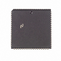
DP83901AV National Semiconductor, DP83901AV Datasheet - Page 44

DP83901AV
Manufacturer Part Number
DP83901AV
Description
IC CONTROLLR SER NETWK IN 68PLCC
Manufacturer
National Semiconductor
Datasheet
1.DP83901AV.pdf
(62 pages)
Specifications of DP83901AV
Controller Type
Serial Network Interface Controller
Interface
Serial
Voltage - Supply
5V
Current - Supply
110mA
Mounting Type
Surface Mount
Package / Case
68-LCC (J-Lead)
Lead Free Status / RoHS Status
Contains lead / RoHS non-compliant
Operating Temperature
-
Other names
*DP83901AV
Available stocks
Company
Part Number
Manufacturer
Quantity
Price
Company:
Part Number:
DP83901AV
Manufacturer:
NS
Quantity:
5 510
Part Number:
DP83901AV
Manufacturer:
NS/国半
Quantity:
20 000
13 0 Bus Arbitration and Timing
Note The dashed lines indicate incorrect timing as described in the text
Write operation could be corrupted This is shown by the
hatched waveforms in the timing diagram of Figure 9 The
execution of the Remote Read can be delayed by the local
DMA operations (particularly during end-of-packet process-
ing)
To ensure the dummy Remote Read does execute a delay
must be inserted between writing the Remote Read Com-
mand and starting to write the Remote Write State Address
(This time is designated in Figure 9 by the delay arrows )
The recommended method to avoid this problem is after the
Remote Read command is given to poll both bytes of the
Current Remote DMA Address Registers When the ad-
dress has incremented PRQ has been set Software should
recognize this and then start the Remote Write
An additional caution for high speed systems is that the
polling must follow guidelines specified in Time Between
Chip Select section That is there must be at least 4 bus
clocks between chip selects (for example when BSCK
MHz then this time should be 200 ns)
FIGURE 9 Timing Diagram for Dummy Remote Read
(Continued)
e
20
44
The general flow for executing a Remote Write is
1 Set Remote Byte Count to a value
2 Issue the ‘‘dummy’’ Remote Read command
3 Read the Current Remote DMA Address (CRDA) (both
4 Compare to previous CRDA value if different go to 6
5 Delay and jump to 3
6 Set up for the Remote Write command by setting the
7 Issue the Remote Write command
Address to unused RAM (one location before the transmit
start address is usually a safe location)
bytes)
Remote Byte Count and the Remote Start Address (note
that if Remote Byte count in step 1 can be set to the
transmit byte count plus one and the Remote Start Ad-
dress to one less these will now be incremented to the
correct values )
l
1 and Remote Start
TL F 10469 – 57


