AD9204-20EBZ Analog Devices Inc, AD9204-20EBZ Datasheet - Page 22
AD9204-20EBZ
Manufacturer Part Number
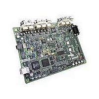
AD9204-20EBZ
Description
BOARD EVALUATION 20MSPS AD9204
Manufacturer
Analog Devices Inc
Datasheet
1.AD9204BCPZ-20.pdf
(36 pages)
Specifications of AD9204-20EBZ
Number Of Adc's
2
Number Of Bits
10
Sampling Rate (per Second)
20M
Data Interface
Serial, SPI™
Inputs Per Adc
1 Differential
Input Range
1 ~ 2 Vpp
Power (typ) @ Conditions
*
Voltage Supply Source
Single Supply
Operating Temperature
-40°C ~ 85°C
Utilized Ic / Part
AD9204
Silicon Manufacturer
Analog Devices
Application Sub Type
ADC
Kit Application Type
Data Converter
Silicon Core Number
AD9204
Tool / Board Applications
General Purpose MCU, MPU, DSP, DSC
Development Tool Type
Hardware / Software - Starter Kit
Lead Free Status / RoHS Status
Lead free / RoHS Compliant


AD9204
VOLTAGE REFERENCE
A stable and accurate 1.0 V voltage reference is built into the
AD9204. The VREF can be configured using either the internal
1.0 V reference or an externally applied 1.0 V reference voltage.
The various reference modes are summarized in the sections that
follow. The Reference Decoupling section describes the best
practices PCB layout of the reference.
Internal Reference Connection
A comparator within the AD9204 detects the potential at the
SENSE pin and configures the reference into two possible
modes, which are summarized in Table 10. If SENSE is grounded,
the reference amplifier switch is connected to the internal resistor
divider (see Figure 46), setting VREF to 1.0 V.
Table 10. Reference Configuration Summary
Selected Mode
Fixed Internal Reference
Fixed External Reference
Table 11. Scaled Differential Span Summary
Selected Mode
Fixed Internal or External Reference
Fixed Internal or External Reference
Fixed Internal or External Reference
Fixed Internal or External Reference
Fixed Internal or External Reference
1.0µF
Figure 46. Internal Reference Configuration
VIN+A/VIN+B
VIN–A/VIN–B
0.1µF
SENSE
VREF
SELECT
SENSE Voltage (V)
AGND to 0.2
AVDD
LOGIC
ADC
Resulting VREF (V)
1.0 (internal or external)
1.0 (internal or external)
1.0 (internal or external)
1.0 (internal or external)
1.0 (internal or external)
0.5V
CORE
ADC
Resulting VREF (V)
1.0 internal
1.0 applied to external VREF pin
Rev. 0 | Page 22 of 36
SPI Register 0x18 (Hex)
0xC0
0xC8
0xD0
0xD8
0xE0
In either internal or external reference mode, the maximum
input range of the ADC can be varied by configuring SPI
Address 0x18 as shown in Table 11, resulting in a selectable
differential span from 1 V p-p to 2 V p-p.
If the internal reference of the AD9204 is used to drive multiple
converters to improve gain matching, the loading of the reference
by the other converters must be considered. Figure 47 shows
how the internal reference voltage is affected by loading.
–0.5
–1.0
–1.5
–2.0
–2.5
–3.0
0
0
0.2
Figure 47. VREF Accuracy vs. Load Current
0.4
Resulting Differential Span (V p-p)
2.0
2.0
0.6
LOAD CURRENT (mA)
Resulting Differential Span (V p-p)
1.0
1.14
1.33
1.6
2.0
INTERNAL V
0.8
1.0
REF
1.2
= 0.993V
1.4
1.6
1.8
2
.0
Related parts for AD9204-20EBZ
Image
Part Number
Description
Manufacturer
Datasheet
Request
R

Part Number:
Description:
10 Bit 40 Msps Dual Low Power ADC
Manufacturer:
Analog Devices Inc
Datasheet:
Part Number:
Description:
10 Bit 65 Msps Dual Low Power ADC
Manufacturer:
Analog Devices Inc
Datasheet:
Part Number:
Description:
10 Bit 80 Msps Dual Low Power ADC
Manufacturer:
Analog Devices Inc
Datasheet:

Part Number:
Description:
±1.7g Dual-Axis IMEMS Accelerometer Evaluation Board
Manufacturer:
Analog Devices Inc
Datasheet:
Part Number:
Description:
Inertial Sensor Evaluation System
Manufacturer:
Analog Devices Inc
Datasheet:
Part Number:
Description:
Manufacturer:
Analog Devices Inc
Datasheet:
Part Number:
Description:
Manufacturer:
Analog Devices Inc
Datasheet:
Part Number:
Description:
Manufacturer:
Analog Devices Inc
Datasheet:
Part Number:
Description:
Manufacturer:
Analog Devices Inc
Datasheet:
Part Number:
Description:
Manufacturer:
Analog Devices Inc
Datasheet:
Part Number:
Description:
Manufacturer:
Analog Devices Inc
Datasheet:
Part Number:
Description:
Manufacturer:
Analog Devices Inc
Datasheet:
Part Number:
Description:
Manufacturer:
Analog Devices Inc
Datasheet: