AD9204-20EBZ Analog Devices Inc, AD9204-20EBZ Datasheet - Page 33
AD9204-20EBZ
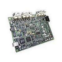
Manufacturer Part Number
AD9204-20EBZ
Description
BOARD EVALUATION 20MSPS AD9204
Manufacturer
Analog Devices Inc
Datasheet
1.AD9204BCPZ-20.pdf
(36 pages)
Specifications of AD9204-20EBZ
Number Of Adc's
2
Number Of Bits
10
Sampling Rate (per Second)
20M
Data Interface
Serial, SPI™
Inputs Per Adc
1 Differential
Input Range
1 ~ 2 Vpp
Power (typ) @ Conditions
*
Voltage Supply Source
Single Supply
Operating Temperature
-40°C ~ 85°C
Utilized Ic / Part
AD9204
Silicon Manufacturer
Analog Devices
Application Sub Type
ADC
Kit Application Type
Data Converter
Silicon Core Number
AD9204
Tool / Board Applications
General Purpose MCU, MPU, DSP, DSC
Development Tool Type
Hardware / Software - Starter Kit
Lead Free Status / RoHS Status
Lead free / RoHS Compliant


Addr
(Hex)
0x0D
0x0E
0x10
0x14
0x15
0x16
0x17
0x18
0x19
0x1A
0x1B
Register
Name
Test mode (local)
BIST enable
Offset adjust
(local)
Output mode
OUTPUT_ADJUST
OUTPUT_PHASE
OUTPUT_DELAY
VREF
USER_PATT1_LSB
USER_PATT1_MSB
USER_PATT2_LSB
Bit 7
(MSB)
User test mode
(local)
00 = single
01 = alternate
10 = single once
11 = alternate
once
Open
8-bit device offset adjustment [7:0] (local)
Offset adjust in LSBs from +127 to −128 (twos complement format)
00 = 3.3 V CMOS
10 = 1.8 V CMOS
3.3 V DCO
drive strength
00 = 1 stripe
(default)
01 = 2 stripes
10 = 3 stripes
11 = 4 stripes
DCO
output
polarity
0 =
normal
1 =
inverted
(local)
Enable
DCO
delay
Reserved =11
B7
B15
B7
Bit 6
B6
B14
B6
Bit 5
Reset PN
long gen
Output mux
enable
(interleaved)
1.8 V DCO
drive strength
00 = 1 stripe
01 = 2 stripes
10 = 3 stripes (default)
11 = 4 stripes
Enable
data
delay
Internal VREF adjustment [2:0]
000 = 1.0 V p-p
001 = 1.14 V p-p
010 = 1.33 V p-p
011 = 1.60 V p-p
100 = 2.0 V p-p
B5
B13
B5
B4
B12
B4
Bit 4
Reset PN
short gen
Output
disable
(local)
Rev. 0 | Page 33 of 36
B3
B11
B3
Bit 3
Output test mode [3:0] (local)
0000 = off (default)
0001 = midscale short
0010 = positive FS
0011 = negative FS
0100 = alternating checkerboard
0101 = PN 23 sequence
0110 = PN 9 sequence
0111 = one/zero word toggle
1000 = user input
1001 = 1-/0-bit toggle
1010 = 1× sync
1011 = one bit high
1100 = mixed bit frequency
Open
Open
3.3 V data
drive strength
00 = 1 stripe
(default)
01 = 2 stripes
10 = 3 stripes
11 = 4 stripes
Input clock phase adjust [2:0]
(Value is number of input clock
cycles of phase delay)
000 = no delay
001 = 1 input clock cycle
010 = 2 input clock cycles
011 = 3 input clock cycles
100 = 4 input clock cycles
101 = 5 input clock cycles
110 = 6 input clock cycles
111 = 7 input clock cycles
DCO/Data delay[2:0]
000 = 0.56 ns
001 = 1.12 ns
010 = 1.68 ns
011 = 2.24 ns
100 = 2.80 ns
101 = 3.36 ns
110 = 3.92 ns
111 = 4.48 ns
B2
B10
B2
Bit 2
BIST INIT
Output
invert
(local)
Bit 1
Open
1.8 V data
drive strength
00 = 1 stripe
01 = 2 stripes
10 = 3 stripes
(default)
11 = 4 stripes
00 = offset binary
01 = twos
complement
10 = gray code
11 = offset binary
(local)
B1
B9
B1
Bit 0
(LSB)
B0
B8
B0
BIST
enable
Default
Value
(Hex)
0x00
0x00
0x00
0x00
0x22
0x00
0x00
0xE0
0x00
0x00
0x00
Comments
When set, the test
data is placed on
the output pins in
place of normal
data
When Bit 0 is set,
the BIST function
is initiated
Device offset trim
Configures the
outputs and the
format of the data
Determines
CMOS output
drive strength
properties
On devices that
utilize global
clock divide,
determines which
phase of the
divider output is
used to supply
the output clock;
internal latching
is unaffected
This sets the fine
output delay of
the output clock
but does not
change internal
timing
Selects and/or
adjusts the VREF
User-defined
pattern, 1 LSB
User-defined
pattern, 1 MSB
User-defined
pattern, 2 LSB
AD9204
Related parts for AD9204-20EBZ
Image
Part Number
Description
Manufacturer
Datasheet
Request
R

Part Number:
Description:
10 Bit 40 Msps Dual Low Power ADC
Manufacturer:
Analog Devices Inc
Datasheet:
Part Number:
Description:
10 Bit 65 Msps Dual Low Power ADC
Manufacturer:
Analog Devices Inc
Datasheet:
Part Number:
Description:
10 Bit 80 Msps Dual Low Power ADC
Manufacturer:
Analog Devices Inc
Datasheet:

Part Number:
Description:
±1.7g Dual-Axis IMEMS Accelerometer Evaluation Board
Manufacturer:
Analog Devices Inc
Datasheet:
Part Number:
Description:
Inertial Sensor Evaluation System
Manufacturer:
Analog Devices Inc
Datasheet:
Part Number:
Description:
Manufacturer:
Analog Devices Inc
Datasheet:
Part Number:
Description:
Manufacturer:
Analog Devices Inc
Datasheet:
Part Number:
Description:
Manufacturer:
Analog Devices Inc
Datasheet:
Part Number:
Description:
Manufacturer:
Analog Devices Inc
Datasheet:
Part Number:
Description:
Manufacturer:
Analog Devices Inc
Datasheet:
Part Number:
Description:
Manufacturer:
Analog Devices Inc
Datasheet:
Part Number:
Description:
Manufacturer:
Analog Devices Inc
Datasheet:
Part Number:
Description:
Manufacturer:
Analog Devices Inc
Datasheet: