CDB5532U Cirrus Logic Inc, CDB5532U Datasheet - Page 29
CDB5532U
Manufacturer Part Number
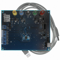
CDB5532U
Description
BOARD EVAL FOR CS5532U ADC
Manufacturer
Cirrus Logic Inc
Specifications of CDB5532U
Number Of Adc's
2
Number Of Bits
24
Sampling Rate (per Second)
3.84k
Data Interface
Serial
Inputs Per Adc
1 Differential
Input Range
±2.5 V
Power (typ) @ Conditions
35mW @ 3.84kSPS
Voltage Supply Source
Analog and Digital, Dual ±
Operating Temperature
-40°C ~ 85°C
Utilized Ic / Part
CS5532
Description/function
Audio DSPs
Operating Supply Voltage
5 V
Product
Audio Modules
For Use With/related Products
C8051F320
Lead Free Status / RoHS Status
Contains lead / RoHS non-compliant
Lead Free Status / RoHS Status
Lead free / RoHS Compliant, Contains lead / RoHS non-compliant
Other names
598-1159


DS755F3
U/B (Unipolar / Bipolar) [22] [6]
OL1-OL0 (Output Latch Bits) [21:20] [5:4]
DT (Delay Time Bit) [19] [3]
OCD (Open Circuit Detect Bit) [18] [2]
OG1-OG0 (Offset / Gain Register Pointer Bits) [17:16] [1:0]
0
1
00
01
10
11
0
1
0
1
00
01
10
11
Select Bipolar mode.
Select Unipolar mode.
The latch bits will be set to the logic state of these bits upon command word execution when the output
latch select bit (OLS) in the configuration register is logic 0. Note that the logic outputs on the chip are
powered from VA+ and VA-.
A0 = 0, A1 = 0
A0 = 0, A1 = 1
A0 = 1, A1 = 0
A0 = 1, A1 = 1
When set, the converter will wait for a delay time before starting a conversion. This allows settling time for
A0 and A1 outputs before a conversion begins. The delay time will be 1280 MCLK cycles when FRS = 0,
and 1536 MCLK cycles when FRS = 1.
Begin Conversions Immediately.
Wait 1280 MCLK cycles (FRS = 0) or 1536 MCLK cycles (FRS = 1) before starting conversion.
When set, this bit activates a 300 nA current source on the input channel (AIN+) selected by the channel
select bits. Note that the 300 nA current source is rated at 25°C. At -55°C, the current source doubles to
approximately 600 nA. This feature is particularly useful in thermocouple applications when the user wants
to drive a suspected open thermocouple lead to a supply rail.
Normal mode.
Activate current source.
These bits are only used when OGS in the Configuration Register is set to ‘1’. They allow the user to select
the offset and gain register to use while performing a conversion or calibration. When the OGS bit in the
Configuration Register is set to ‘0’, the offset and gain register for the referenced physical channel (CS1-
CS0 bits of the Setup) will be used.
Use offset and gain register from physical channel 1
Use offset and gain register from physical channel 2
Use offset and gain register from physical channel 3
Use offset and gain register from physical channel 4
CS5532/34-BS
29
Related parts for CDB5532U
Image
Part Number
Description
Manufacturer
Datasheet
Request
R

Part Number:
Description:
Development Kit
Manufacturer:
Cirrus Logic Inc
Datasheet:
Part Number:
Description:
Development Kit
Manufacturer:
Cirrus Logic Inc
Datasheet:


Part Number:
Description:
High-efficiency PFC + Fluorescent Lamp Driver Reference Design
Manufacturer:
Cirrus Logic Inc
Datasheet:
Part Number:
Description:
Development Kit
Manufacturer:
Cirrus Logic Inc
Datasheet:
Part Number:
Description:
Development Kit
Manufacturer:
Cirrus Logic Inc
Datasheet:

Part Number:
Description:
Development Kit
Manufacturer:
Cirrus Logic Inc
Datasheet:
Part Number:
Description:
Development Kit
Manufacturer:
Cirrus Logic Inc
Datasheet:
Part Number:
Description:
Development Kit
Manufacturer:
Cirrus Logic Inc
Datasheet:
Part Number:
Description:
Development Kit
Manufacturer:
Cirrus Logic Inc
Datasheet:

Part Number:
Description:
EVALUATION BOARD FOR CS8427
Manufacturer:
Cirrus Logic Inc
Datasheet:

Part Number:
Description:
BOARD EVAL FOR CS8416 RCVR
Manufacturer:
Cirrus Logic Inc
Datasheet:

Part Number:
Description:
EVALUATION BOARD FOR CS8420
Manufacturer:
Cirrus Logic Inc
Datasheet:

Part Number:
Description:
KIT DEVELOPMENT EP9315 ARM9
Manufacturer:
Cirrus Logic Inc
Datasheet:

Part Number:
Description:
KIT DEVELOPMENT EP9302 ARM9
Manufacturer:
Cirrus Logic Inc
Datasheet: