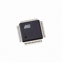
AT91SAM7S32B-AU Atmel, AT91SAM7S32B-AU Datasheet - Page 364

AT91SAM7S32B-AU
Manufacturer Part Number
AT91SAM7S32B-AU
Description
IC MCU ARM7 32KB FLASH 48LQFP
Manufacturer
Atmel
Series
AT91SAMr
Datasheet
1.AT91SAM7S16-MU.pdf
(779 pages)
Specifications of AT91SAM7S32B-AU
Core Processor
ARM7
Core Size
16/32-Bit
Speed
55MHz
Connectivity
I²C, SPI, SSC, UART/USART
Peripherals
Brown-out Detect/Reset, DMA, POR, PWM, WDT
Number Of I /o
21
Program Memory Size
32KB (32K x 8)
Program Memory Type
FLASH
Ram Size
8K x 8
Voltage - Supply (vcc/vdd)
1.65 V ~ 1.95 V
Data Converters
A/D 8x10b
Oscillator Type
Internal
Operating Temperature
-40°C ~ 85°C
Package / Case
48-LQFP
Cpu Family
91S
Device Core
ARM7TDMI
Device Core Size
32b
Frequency (max)
55MHz
Interface Type
SPI/TWI/USART
Total Internal Ram Size
8KB
# I/os (max)
21
Number Of Timers - General Purpose
3
Operating Supply Voltage (typ)
1.8/3.3V
Operating Supply Voltage (max)
1.95/3.6V
Operating Supply Voltage (min)
1.65/3V
On-chip Adc
8-chx10-bit
Instruction Set Architecture
RISC
Operating Temp Range
-40C to 85C
Operating Temperature Classification
Industrial
Mounting
Surface Mount
Pin Count
48
Package Type
LQFP
Package
48LQFP
Family Name
AT91
Maximum Speed
55 MHz
Operating Supply Voltage
1.8|3.3 V
Data Bus Width
32 Bit
Number Of Programmable I/os
21
Number Of Timers
3
For Use With
AT91SAM-ICE - EMULATOR FOR AT91 ARM7/ARM9AT91SAM7S-EK - KIT EVAL FOR ARM AT91SAM7S
Lead Free Status / RoHS Status
Lead free / RoHS Compliant
Eeprom Size
-
Lead Free Status / Rohs Status
Compliant
Available stocks
Company
Part Number
Manufacturer
Quantity
Price
Part Number:
AT91SAM7S32B-AU
Manufacturer:
MICROCHIP/微芯
Quantity:
20 000
- Current page: 364 of 779
- Download datasheet (11Mb)
Table 31-3.
Table 31-4.
Table 31-5.
364
DI field
Di (decimal)
FI field
Fi (decimal
Fi/Di
16
32
12
20
1
2
4
8
AT91SAM7S Series Preliminary
23.25
11.62
46.5
18.6
Binary and Decimal Values for Di
Binary and Decimal Values for Fi
Possible Values for the Fi/Di Ratio
372
372
186
0000
93
31
372
0001
1
0001
139.5
69.75
34.87
17.43
372
46.5
27.9
558
558
279
Di is a binary value encoded on a 4-bit field, named DI, as represented in
Fi is a binary value encoded on a 4-bit field, named FI, as represented in
Table 31-5
baud rate clock.
If the USART is configured in ISO7816 Mode, the clock selected by the USCLKS field in the
Mode Register (US_MR) is first divided by the value programmed in the field CD in the Baud
Rate Generator Register (US_BRGR). The resulting clock can be provided to the SCK pin to
feed the smart card clock inputs. This means that the CLKO bit can be set in US_MR.
This clock is then divided by the value programmed in the FI_DI_RATIO field in the FI_DI_Ratio
register (US_FIDI). This is performed by the Sampling Divider, which performs a division by up
to 2047 in ISO7816 Mode. The non-integer values of the Fi/Di Ratio are not supported and the
user must program the FI_DI_RATIO field to a value as close as possible to the expected value.
The FI_DI_RATIO field resets to the value 0x174 (372 in decimal) and is the most common
divider between the ISO7816 clock and the bit rate (Fi = 372, Di = 1).
Figure 31-7
and the ISO 7816 clock.
0010
0010
558
2
23.25
46.5
37.2
774
744
372
186
93
62
shows the resulting Fi/Di Ratio, which is the ratio between the ISO7816 clock and the
shows the relation between the Elementary Time Unit, corresponding to a bit time,
0011
744
69.75
139.5
34.87
1116
1116
55.8
558
279
0011
93
4
1116
0100
1488
1488
46.5
74.4
744
372
186
124
93
0100
0101
1488
8
232.5
116.2
58.13
1806
1860
930
465
155
93
0110
1860
0101
16
42.66
25.6
512
512
256
128
64
32
16
1001
512
0110
38.4
768
768
384
192
96
48
24
64
32
1010
768
85.33
1024
1024
51.2
512
256
128
64
32
1011
1024
1000
Table
12
Table
6175K–ATARM–30-Aug-10
1536
1536
76.8
31-4.
768
384
192
128
31-3.
1100
1536
96
48
1001
20
170.6
102.4
2048
2048
1024
1101
2048
512
256
128
64
Related parts for AT91SAM7S32B-AU
Image
Part Number
Description
Manufacturer
Datasheet
Request
R

Part Number:
Description:
KIT EVAL FOR ARM AT91SAM7S
Manufacturer:
Atmel
Datasheet:

Part Number:
Description:
MCU, MPU & DSP Development Tools KICKSTART KIT ATMEL AT91SAM7S
Manufacturer:
IAR Systems

Part Number:
Description:
DEV KIT FOR AVR/AVR32
Manufacturer:
Atmel
Datasheet:

Part Number:
Description:
INTERVAL AND WIPE/WASH WIPER CONTROL IC WITH DELAY
Manufacturer:
ATMEL Corporation
Datasheet:

Part Number:
Description:
Low-Voltage Voice-Switched IC for Hands-Free Operation
Manufacturer:
ATMEL Corporation
Datasheet:

Part Number:
Description:
MONOLITHIC INTEGRATED FEATUREPHONE CIRCUIT
Manufacturer:
ATMEL Corporation
Datasheet:

Part Number:
Description:
AM-FM Receiver IC U4255BM-M
Manufacturer:
ATMEL Corporation
Datasheet:

Part Number:
Description:
Monolithic Integrated Feature Phone Circuit
Manufacturer:
ATMEL Corporation
Datasheet:

Part Number:
Description:
Multistandard Video-IF and Quasi Parallel Sound Processing
Manufacturer:
ATMEL Corporation
Datasheet:

Part Number:
Description:
High-performance EE PLD
Manufacturer:
ATMEL Corporation
Datasheet:

Part Number:
Description:
8-bit Flash Microcontroller
Manufacturer:
ATMEL Corporation
Datasheet:

Part Number:
Description:
2-Wire Serial EEPROM
Manufacturer:
ATMEL Corporation
Datasheet:


