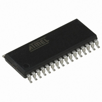
AT90PWM3-16SQ Atmel, AT90PWM3-16SQ Datasheet - Page 2

AT90PWM3-16SQ
Manufacturer Part Number
AT90PWM3-16SQ
Description
IC AVR MCU FLASH 8K 32SOIC
Manufacturer
Atmel
Series
AVR® 90PWM Lightingr
Datasheet
1.AT90PWM3B-16SU.pdf
(361 pages)
Specifications of AT90PWM3-16SQ
Core Processor
AVR
Core Size
8-Bit
Speed
16MHz
Connectivity
SPI, UART/USART
Peripherals
Brown-out Detect/Reset, POR, PWM, WDT
Number Of I /o
27
Program Memory Size
8KB (8K x 8)
Program Memory Type
FLASH
Eeprom Size
512 x 8
Ram Size
512 x 8
Voltage - Supply (vcc/vdd)
2.7 V ~ 5.5 V
Data Converters
A/D 11x10b; D/A 1x10b
Oscillator Type
Internal
Operating Temperature
-40°C ~ 105°C
Package / Case
32-SOIC (7.5mm Width)
Processor Series
AT90PWMx
Core
AVR8
Data Bus Width
8 bit
Data Ram Size
512 B
Interface Type
SPI, USART
Maximum Clock Frequency
16 MHz
Number Of Programmable I/os
27
Number Of Timers
2
Operating Supply Voltage
2.7 V to 5.5 V
Maximum Operating Temperature
+ 105 C
Mounting Style
SMD/SMT
3rd Party Development Tools
EWAVR, EWAVR-BL
Development Tools By Supplier
ATAVRDRAGON, ATSTK500, ATSTK600, ATAVRISP2, ATAVRONEKIT, ATAVRFBKIT, ATAVRISP2
Minimum Operating Temperature
- 40 C
On-chip Adc
10 bit, 11 Channel
On-chip Dac
10 bit, 1 Channel
For Use With
ATSTK600-SOIC - STK600 SOCKET/ADAPTER FOR SOICATAVRMC200 - KIT EVAL FOR AT90PWM3 ASYNCATAVRFBKIT - KIT DEMO BALLAST FOR AT90PWM2ATSTK520 - ADAPTER KIT FOR 90PWM
Lead Free Status / RoHS Status
Lead free / RoHS Compliant
- Current page: 2 of 361
- Download datasheet (7Mb)
•
•
1. History
2. Disclaimer
2
Product
AT90PWM2
AT90PWM2B
AT90PWM3
AT90PWM3B
Operating Voltage: 2.7V - 5.5V
Extended Operating Temperature:
– In-System Programmable via SPI Port
– Internal Calibrated RC Oscillator ( 8 MHz)
– On-chip PLL for fast PWM ( 32 MHz, 64 MHz) and CPU (16 MHz)
– -40°C to +105°C
AT90PWM2/3/2B/3B
Package
SO24
SO32,
QFN32
This datasheet deals with product characteristics of AT90PW2 and AT90WM3. It will be updated
as soon as characterization will be done.
Typical values contained in this datasheet are based on simulations and characterization of
other AVR microcontrollers manufactured on the same process technology. Min and Max val-
ues will be available after the device is characterized.
Product
AT90PWM2
AT90PWM3
AT90PWM2B
AT90PWM3B
12 bit PWM with
deadtime
2 x 2
3 x 2
Revision
First revision of parts, only for running production.
Second revision of parts, for all new developments.
The major changes are :
• complement the PSCOUT01, PSCOUT11, PSCOUT21 polarity in
• Add the PSC software triggering capture -
• Add bits to read the PSC output activity -
• Add some clock configurations -
• Change Amplifier Synchonization -
• Correction of the Errata -
centered mode -
Aligned Mode” on page 138.
Register – PICR0H and PICR0L” on page 169.
Register – PIFR0” on page 171.
AT90PWM2B/3B” on page 30.
See “” on page 253.
ADC
Input
8
11
ADC
Diff
1
2
See “PSCn0 & PSCn1 Basic Waveforms in Center
See “Errata” on page 348.
Analog
Compar
2
3
See “Device Clocking Options Select
See “Amplifier” on page 251.
See “PSC0 Interrupt Flag
See “PSC 0 Input Capture
Application
One fluorescent ballast
HID ballast, fluorescent ballast,
Motor control
4317J–AVR–08/10
and
Related parts for AT90PWM3-16SQ
Image
Part Number
Description
Manufacturer
Datasheet
Request
R

Part Number:
Description:
IC AVR MCU FLASH 8K 32QFN
Manufacturer:
Atmel
Datasheet:

Part Number:
Description:
MCU AVR 8K FLASH 16MHZ 32-QFN
Manufacturer:
Atmel
Datasheet:

Part Number:
Description:
DEV KIT FOR AVR/AVR32
Manufacturer:
Atmel
Datasheet:

Part Number:
Description:
INTERVAL AND WIPE/WASH WIPER CONTROL IC WITH DELAY
Manufacturer:
ATMEL Corporation
Datasheet:

Part Number:
Description:
Low-Voltage Voice-Switched IC for Hands-Free Operation
Manufacturer:
ATMEL Corporation
Datasheet:

Part Number:
Description:
MONOLITHIC INTEGRATED FEATUREPHONE CIRCUIT
Manufacturer:
ATMEL Corporation
Datasheet:

Part Number:
Description:
AM-FM Receiver IC U4255BM-M
Manufacturer:
ATMEL Corporation
Datasheet:

Part Number:
Description:
Monolithic Integrated Feature Phone Circuit
Manufacturer:
ATMEL Corporation
Datasheet:

Part Number:
Description:
Multistandard Video-IF and Quasi Parallel Sound Processing
Manufacturer:
ATMEL Corporation
Datasheet:

Part Number:
Description:
High-performance EE PLD
Manufacturer:
ATMEL Corporation
Datasheet:

Part Number:
Description:
8-bit Flash Microcontroller
Manufacturer:
ATMEL Corporation
Datasheet:

Part Number:
Description:
2-Wire Serial EEPROM
Manufacturer:
ATMEL Corporation
Datasheet:


