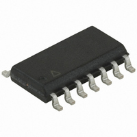
ATTINY24-15SSZ Atmel, ATTINY24-15SSZ Datasheet - Page 136

ATTINY24-15SSZ
Manufacturer Part Number
ATTINY24-15SSZ
Description
MCU AVR 2K FLASH 15MHZ 14-SOIC
Manufacturer
Atmel
Series
AVR® ATtinyr
Datasheet
1.ATTINY24-15SSZ.pdf
(225 pages)
Specifications of ATTINY24-15SSZ
Package / Case
14-SOIC (3.9mm Width), 14-SOL
Voltage - Supply (vcc/vdd)
2.7 V ~ 5.5 V
Operating Temperature
-40°C ~ 125°C
Speed
16MHz
Number Of I /o
12
Eeprom Size
128 x 8
Core Processor
AVR
Program Memory Type
FLASH
Ram Size
128 x 8
Program Memory Size
2KB (2K x 8)
Data Converters
A/D 8x10b
Oscillator Type
Internal
Peripherals
Brown-out Detect/Reset, POR, PWM, WDT
Connectivity
USI
Core Size
8-Bit
Cpu Family
ATtiny
Device Core
AVR
Device Core Size
8b
Frequency (max)
16MHz
Interface Type
SPI/UART
Total Internal Ram Size
128Byte
# I/os (max)
12
Number Of Timers - General Purpose
2
Operating Supply Voltage (typ)
3.3/5V
Operating Supply Voltage (max)
5.5V
Operating Supply Voltage (min)
2.7V
On-chip Adc
8-chx10-bit
Instruction Set Architecture
RISC
Operating Temp Range
-40C to 125C
Operating Temperature Classification
Automotive
Mounting
Surface Mount
Pin Count
14
Package Type
SOIC
Lead Free Status / RoHS Status
Lead free / RoHS Compliant
Available stocks
Company
Part Number
Manufacturer
Quantity
Price
Company:
Part Number:
ATTINY24-15SSZ
Manufacturer:
ATMEL
Quantity:
349
Part Number:
ATTINY24-15SSZ
Manufacturer:
ATTINY
Quantity:
20 000
- Current page: 136 of 225
- Download datasheet (4Mb)
18. Analog-to-Digital Converter
18.1
18.2
136
Features
Overview
Atmel ATtiny24/44/84 [Preliminary]
•
•
•
•
•
•
•
•
•
•
•
•
•
•
•
•
•
The Atmel
verter (ADC). The ADC is connected to 8-pin port A for external sources. In addition to
external sources, the internal temperature sensor can be measured by the ADC. The analog
multiplexer allows 8 single-ended channels or 12 differential channels from port A. The pro-
grammable gain stage provides amplification steps 0dB (1x) and 26dB (20x) for 12 differential
ADC channels.
The ADC contains a sample-and-hold circuit which ensures that the input voltage to the ADC
is held at a constant level during conversion. A block diagram of the ADC is shown in
18-1 on page
And internal reference voltage of nominally 1.1V is provided on chip. Alternatively, VCC can
be used as reference voltage for single-ended channels. There is also an option to use an
external voltage reference and turn off the internal voltage reference.
10-bit Resolution
1.0 LSB Integral Non-linearity
±2 LSB Absolute Accuracy
65 - 260µs Conversion Time
Up to 76kSPS at Maximum Resolution
Eight Multiplexed Single-Ended Input Channels
Twelve differential input channels with selectable gain (1x, 20x)
Temperature sensor input channel
Optional Left Adjustment for ADC Result Readout
0 - V
1.1V ADC Reference Voltage
Free-Running or Single-Conversion Mode
ADC Start Conversion by Auto Triggering on Interrupt Sources
Interrupt on ADC Conversion Complete
Sleep Mode Noise Canceller
Unipolar / Bipolar Input Mode
Input Polarity Reversal channels
CC
ADC Input Voltage Range
®
ATtiny24/44/84 features a 10-bit successive approximation analog-to-digital con-
137.
7701D–AVR–09/10
Figure
Related parts for ATTINY24-15SSZ
Image
Part Number
Description
Manufacturer
Datasheet
Request
R

Part Number:
Description:
Manufacturer:
Atmel Corporation
Datasheet:

Part Number:
Description:
Manufacturer:
Atmel Corporation
Datasheet:

Part Number:
Description:
IC MCU AVR 2K FLASH 20MHZ 20-QFN
Manufacturer:
Atmel
Datasheet:

Part Number:
Description:
IC MCU AVR 2K FLASH 20MHZ 14SOIC
Manufacturer:
Atmel
Datasheet:

Part Number:
Description:
MCU AVR 2K FLASH 15MHZ 20-QFN
Manufacturer:
Atmel
Datasheet:

Part Number:
Description:
IC MCU AVR 2K FLASH 20MHZ 14-DIP
Manufacturer:
Atmel
Datasheet:

Part Number:
Description:
MCU AVR 2KB FLASH 20MHZ 14SOIC
Manufacturer:
Atmel
Datasheet:

Part Number:
Description:
MCU AVR 2KB FLASH 20MHZ 20QFN
Manufacturer:
Atmel
Datasheet:

Part Number:
Description:
IC, MCU, 8BIT, 2K FLASH, 20SOIC
Manufacturer:
Atmel
Datasheet:

Part Number:
Description:
IC, MCU, 8BIT, 2K FLASH, 20PDIP
Manufacturer:
Atmel
Datasheet:

Part Number:
Description:
IC, MCU, 8BIT, 8K FLASH, 20PDIP
Manufacturer:
Atmel
Datasheet:

Part Number:
Description:
IC, MCU, 8BIT, 8K FLASH, 20SOIC
Manufacturer:
Atmel
Datasheet:


