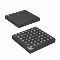
ATXMEGA16A4-CU Atmel, ATXMEGA16A4-CU Datasheet - Page 262

ATXMEGA16A4-CU
Manufacturer Part Number
ATXMEGA16A4-CU
Description
MCU AVR 16+4KB FLASH 49VFBGA
Manufacturer
Atmel
Series
AVR® XMEGAr
Specifications of ATXMEGA16A4-CU
Core Processor
AVR
Core Size
8/16-Bit
Speed
32MHz
Connectivity
I²C, IrDA, SPI, UART/USART
Peripherals
Brown-out Detect/Reset, DMA, POR, PWM, WDT
Number Of I /o
34
Program Memory Size
16KB (8K x 16)
Program Memory Type
FLASH
Eeprom Size
1K x 8
Ram Size
2K x 8
Voltage - Supply (vcc/vdd)
1.6 V ~ 3.6 V
Data Converters
A/D 12x12b, D/A 2x12b
Oscillator Type
Internal
Operating Temperature
-40°C ~ 85°C
Package / Case
49-VFBGA
Processor Series
ATXMEGA16x
Core
AVR8
Data Bus Width
8 bit, 16 bit
Data Ram Size
2 KB
Interface Type
I2C/SPI/USART
Maximum Clock Frequency
32 MHz
Number Of Programmable I/os
34
Number Of Timers
5
Operating Supply Voltage
1.6 V to 3.6 V
Maximum Operating Temperature
+ 85 C
Mounting Style
SMD/SMT
3rd Party Development Tools
EWAVR, EWAVR-BL
Development Tools By Supplier
ATAVRDRAGON, ATAVRISP2, ATAVRONEKIT
Minimum Operating Temperature
- 40 C
On-chip Adc
12-ch x 12-bit
On-chip Dac
2-ch x 12-bit
For Use With
ATAVRONEKIT - KIT AVR/AVR32 DEBUGGER/PROGRMMRATSTK600 - DEV KIT FOR AVR/AVR32770-1007 - ISP 4PORT ATMEL AVR MCU SPI/JTAG770-1004 - ISP 4PORT FOR ATMEL AVR MCU SPI
Lead Free Status / RoHS Status
Lead free / RoHS Compliant
Available stocks
Company
Part Number
Manufacturer
Quantity
Price
- Current page: 262 of 445
- Download datasheet (6Mb)
23.4.1
8077H–AVR–12/09
Key and State Memory
The following procedure for setup and use is recommended:
If more than one block is to be encrypted or decrypted repeat the procedure from step 3.
When the encryption/decryption procedure is complete the AES Interrupt Flag is set and the
optional interrupt is generated.
The AES Key and State memory are both 16 x 8-bit memories that are accessible through the
Key (KEY) and State (STATE) register, respectively.
Each memory has two 4-bit address pointers used to address the memory for read and write,
respectively. The initial value of the pointers are zero. After a read or write operation to the State
or Key register, the appropriate pointer is automatically incremented. Accessing (read or write)
the Control Register (CTRL) will reset all pointers to zero. A pointer overflow (a sequential read
or write is done more than 16 times) will also set the affected pointer to zero. The address point-
ers are not accessible from software. Read and write memory pointers are both incremented
during write operations in XOR mode.
Access to the Key and State registers are only possible when encryption/decryption is not in
progress.
Figure 23-2. The State memory with pointers and register
1. Enable AES interrupts (optional)
2. Select the AES direction, encryption or decryption.
3. Load the Key data block into the AES Key memory
4. Load the data block into the AES State memory
5. Start the encryption/decryption operation
address pointer
4-bit state write
reset or access
Reset pointer
to AES Control
I/O Data Bus
XOR
STATE
14
15
0
1
-
xor
STATE[read pointer]
address pointer
4-bit state read
reset or access
to AES Control
Reset pointer
XMEGA A
262
Related parts for ATXMEGA16A4-CU
Image
Part Number
Description
Manufacturer
Datasheet
Request
R

Part Number:
Description:
DEV KIT FOR AVR/AVR32
Manufacturer:
Atmel
Datasheet:

Part Number:
Description:
INTERVAL AND WIPE/WASH WIPER CONTROL IC WITH DELAY
Manufacturer:
ATMEL Corporation
Datasheet:

Part Number:
Description:
Low-Voltage Voice-Switched IC for Hands-Free Operation
Manufacturer:
ATMEL Corporation
Datasheet:

Part Number:
Description:
MONOLITHIC INTEGRATED FEATUREPHONE CIRCUIT
Manufacturer:
ATMEL Corporation
Datasheet:

Part Number:
Description:
AM-FM Receiver IC U4255BM-M
Manufacturer:
ATMEL Corporation
Datasheet:

Part Number:
Description:
Monolithic Integrated Feature Phone Circuit
Manufacturer:
ATMEL Corporation
Datasheet:

Part Number:
Description:
Multistandard Video-IF and Quasi Parallel Sound Processing
Manufacturer:
ATMEL Corporation
Datasheet:

Part Number:
Description:
High-performance EE PLD
Manufacturer:
ATMEL Corporation
Datasheet:

Part Number:
Description:
8-bit Flash Microcontroller
Manufacturer:
ATMEL Corporation
Datasheet:

Part Number:
Description:
2-Wire Serial EEPROM
Manufacturer:
ATMEL Corporation
Datasheet:


