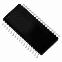
ST72F621L4M1 STMicroelectronics, ST72F621L4M1 Datasheet - Page 104

ST72F621L4M1
Manufacturer Part Number
ST72F621L4M1
Description
IC MCU 8BIT LS 16K 34-SOIC
Manufacturer
STMicroelectronics
Series
ST7r
Datasheet
1.ST72F622L2M1.pdf
(139 pages)
Specifications of ST72F621L4M1
Core Processor
ST7
Core Size
8-Bit
Speed
8MHz
Connectivity
SCI, SPI, USB
Peripherals
DMA, LVD, POR, PWM, WDT
Number Of I /o
23
Program Memory Size
16KB (16K x 8)
Program Memory Type
FLASH
Ram Size
768 x 8
Voltage - Supply (vcc/vdd)
4 V ~ 5.5 V
Data Converters
A/D 8x10b
Oscillator Type
Internal
Operating Temperature
0°C ~ 70°C
Package / Case
34-SOIC (7.5mm Width)
Processor Series
ST72F6x
Core
ST7
Data Bus Width
8 bit
Data Ram Size
768 B
Interface Type
SCI, SPI, USB
Maximum Clock Frequency
12 MHz
Number Of Programmable I/os
23
Number Of Timers
2
Operating Supply Voltage
4 V to 5.5 V
Maximum Operating Temperature
+ 70 C
Mounting Style
SMD/SMT
Minimum Operating Temperature
0 C
On-chip Adc
10 bit
For Use With
497-5046 - KIT TOOL FOR ST7/UPSD/STR7 MCU
Lead Free Status / RoHS Status
Lead free / RoHS Compliant
Eeprom Size
-
Lead Free Status / Rohs Status
In Transition
Other names
497-2112-5
Available stocks
Company
Part Number
Manufacturer
Quantity
Price
Company:
Part Number:
ST72F621L4M1
Manufacturer:
ST
Quantity:
2 272
Company:
Part Number:
ST72F621L4M1
Manufacturer:
ST
Quantity:
5
12.4 SUPPLY CURRENT CHARACTERISTICS
The following current consumption specified for
the ST7 functional operating modes over tempera-
ture range does not take into account the clock
source current consumption. To get the total de-
vice consumption, the two current values must be
Note 1:
Note 2:
Note 3:
Note 4:
Figure 56. Typ. I
104/139
ΔI
Symbol
I
DD(ADC)
DD(ΔTa)
I
DD
12
10
8
6
4
2
0
Typical data are based on T
Data based on design simulation, not tested in production.
USB Transceiver and ADC are powered down.
Low voltage reset function enabled.
CPU in HALT mode.
Current consumption of external pull-up (1.5Kohms to USBVCC) and pull-down (15Kohms to V
not included.
3
Supply current variation vs. temperature Constant V
ADC supply current when converting
3.5
4
DD
Vdd (V)
USB Suspend mode
CPU HALT mode
CPU WAIT mode
4.5
CPU RUN mode
in RUN at 4 and 8 MHz f
Parameter
5
5.5
6
A
2)
=25°C and not tested in production
3)
4)
Idd run at
fcpu=4 MHz
Idd run at
fcpu=8 MHz
CPU
LVD enabled. USB in
LVD enabled. USB in
USB transceiver and
USB transceiver and
I/Os in input mode.
I/Os in input mode.
Transmission
Doc ID 6996 Rev 5
LVD disabled
LVD disabled
Transmission
without LVD
with LVD
added (except for HALT mode for which the clock
is stopped).
Figure 57. Typ. I
DD
10
9
8
7
6
5
4
3
2
1
0
Conditions
f
ADC
and f
1
2)
=4MHz
CPU
2
f
f
f
f
f
f
CPU
CPU
CPU
CPU
CPU
CPU
3
Vdd (V)
DD
= 4 MHz
= 8 MHz
= 4 MHz
= 8 MHz
= 8 MHz
= 8 MHz
4
in WAIT at 4 and 8 MHz f
5
6
1000
Typ
130
130
13
15
14
30
6
8
7
7
1)
2)
Max
200
200
10
14
18
24
12
22
50
SSA
8
Idd wfi at fcpu=4
MHz
Idd wfi at fcpu=8
MHz
)
Unit
mA
mA
mA
mA
mA
μA
μA
μA
%
CPU


