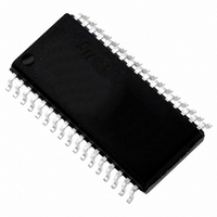
ST72F621L4M1 STMicroelectronics, ST72F621L4M1 Datasheet - Page 28

ST72F621L4M1
Manufacturer Part Number
ST72F621L4M1
Description
IC MCU 8BIT LS 16K 34-SOIC
Manufacturer
STMicroelectronics
Series
ST7r
Datasheet
1.ST72F622L2M1.pdf
(139 pages)
Specifications of ST72F621L4M1
Core Processor
ST7
Core Size
8-Bit
Speed
8MHz
Connectivity
SCI, SPI, USB
Peripherals
DMA, LVD, POR, PWM, WDT
Number Of I /o
23
Program Memory Size
16KB (16K x 8)
Program Memory Type
FLASH
Ram Size
768 x 8
Voltage - Supply (vcc/vdd)
4 V ~ 5.5 V
Data Converters
A/D 8x10b
Oscillator Type
Internal
Operating Temperature
0°C ~ 70°C
Package / Case
34-SOIC (7.5mm Width)
Processor Series
ST72F6x
Core
ST7
Data Bus Width
8 bit
Data Ram Size
768 B
Interface Type
SCI, SPI, USB
Maximum Clock Frequency
12 MHz
Number Of Programmable I/os
23
Number Of Timers
2
Operating Supply Voltage
4 V to 5.5 V
Maximum Operating Temperature
+ 70 C
Mounting Style
SMD/SMT
Minimum Operating Temperature
0 C
On-chip Adc
10 bit
For Use With
497-5046 - KIT TOOL FOR ST7/UPSD/STR7 MCU
Lead Free Status / RoHS Status
Lead free / RoHS Compliant
Eeprom Size
-
Lead Free Status / Rohs Status
In Transition
Other names
497-2112-5
Available stocks
Company
Part Number
Manufacturer
Quantity
Price
Company:
Part Number:
ST72F621L4M1
Manufacturer:
ST
Quantity:
2 272
Company:
Part Number:
ST72F621L4M1
Manufacturer:
ST
Quantity:
5
ST7262xxx
INTERRUPTS (Cont’d)
INTERRUPT REGISTER 1 (ITRFRE1)
Address: 0008h - Read/Write
Reset Value: 0000 0000 (00h)
Bit 7:0 = ITiE Interrupt Enable
0: I/O pin free for general purpose I/O
1: ITi external interrupt enabled.
Note: The corresponding interrupt is generated
when:
– a rising edge occurs on the IT5/IT6 pins
– a falling edge occurs on the IT1, 2, 3, 4, 7 and 8
INTERRUPT REGISTER 2 (ITRFRE2)
Address: 0039h - Read/Write
Reset Value: 0000 0000 (00h)
Bit 7:6 = CTL[3:2] IT[12:11] Interrupt Sensitivity
These bits are set and cleared by software. They
are used to configure the edge and level sensitivity
of the IT12 and IT11 external interrupt pins (this
means that both must have the same sensitivity).
28/139
CTL3 CTL2 CTL1 CTL0 IT12E IT11E IT10E IT9E
IT8E
CTL3
0
0
1
1
pins
7
7
IT7E
CTL2
0
1
0
1
IT6E
IT[12:11] Sensitivity
Falling edge and low level
Rising edge only
Falling edge only
Rising and falling edge
IT5E
IT4E
IT3E
IT2E
IT1E
0
0
Doc ID 6996 Rev 5
Bit 5:4 = CTL[1:0] IT[10:9]1nterrupt Sensitivity
These bits are set and cleared by software. They
are used to configure the edge and level sensitivity
of the IT10 and IT9 external interrupt pins (this
means that both must have the same sensitivity).
Bit 3:0 = ITiE Interrupt Enable
0: I/O pin free for general purpose I/O
1: ITi external interrupt enabled.
CTL1
0
0
1
1
CTL0
0
1
0
1
IT[10:9] Sensitivity
Falling edge and low level
Rising edge only
Falling edge only
Rising and falling edge


