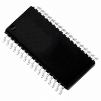
ST72F621L4M1 STMicroelectronics, ST72F621L4M1 Datasheet - Page 84

ST72F621L4M1
Manufacturer Part Number
ST72F621L4M1
Description
IC MCU 8BIT LS 16K 34-SOIC
Manufacturer
STMicroelectronics
Series
ST7r
Datasheet
1.ST72F622L2M1.pdf
(139 pages)
Specifications of ST72F621L4M1
Core Processor
ST7
Core Size
8-Bit
Speed
8MHz
Connectivity
SCI, SPI, USB
Peripherals
DMA, LVD, POR, PWM, WDT
Number Of I /o
23
Program Memory Size
16KB (16K x 8)
Program Memory Type
FLASH
Ram Size
768 x 8
Voltage - Supply (vcc/vdd)
4 V ~ 5.5 V
Data Converters
A/D 8x10b
Oscillator Type
Internal
Operating Temperature
0°C ~ 70°C
Package / Case
34-SOIC (7.5mm Width)
Processor Series
ST72F6x
Core
ST7
Data Bus Width
8 bit
Data Ram Size
768 B
Interface Type
SCI, SPI, USB
Maximum Clock Frequency
12 MHz
Number Of Programmable I/os
23
Number Of Timers
2
Operating Supply Voltage
4 V to 5.5 V
Maximum Operating Temperature
+ 70 C
Mounting Style
SMD/SMT
Minimum Operating Temperature
0 C
On-chip Adc
10 bit
For Use With
497-5046 - KIT TOOL FOR ST7/UPSD/STR7 MCU
Lead Free Status / RoHS Status
Lead free / RoHS Compliant
Eeprom Size
-
Lead Free Status / Rohs Status
In Transition
Other names
497-2112-5
Available stocks
Company
Part Number
Manufacturer
Quantity
Price
Company:
Part Number:
ST72F621L4M1
Manufacturer:
ST
Quantity:
2 272
Company:
Part Number:
ST72F621L4M1
Manufacturer:
ST
Quantity:
5
ST7262xxx
USB INTERFACE (Cont’d)
10.6.4 Register Description
DMA ADDRESS REGISTER (DMAR)
Read / Write
Reset Value: Undefined
Bits 7:0=DA[15:8] DMA address bits 15-8.
Software must write the start address of the DMA
memory area whose most significant bits are given
by DA15-DA6. The remaining 6 address bits are
set by hardware. See the description of the IDR
register and
Figure 51. DMA Buffers
84/139
DA15
7
DA14
Figure
DA13
DA15-6,000000
DA12
51.
DA11
DA10
DA9
DA8
0
101111
101000
100111
100000
011111
011000
010111
010000
001111
001000
000111
000000
Doc ID 6996 Rev 5
INTERRUPT/DMA REGISTER (IDR)
Read / Write
Reset Value: xxxx 0000 (x0h)
Bits 7:6 = DA[7:6] DMA address bits 7-6.
Software must reset these bits. See the descrip-
tion of the DMAR register and
Bits 5:4 = EP[1:0] Endpoint number (read-only).
These bits identify the endpoint which required at-
tention.
00: Endpoint 0
01: Endpoint 1
10: Endpoint 2
When a CTR interrupt occurs (see register ISTR)
the software should read the EP bits to identify the
endpoint which has sent or received a packet.
Bits 3:0 = CNT[3:0] Byte count (read only).
This field shows how many data bytes have been
received during the last data reception.
Note: Not valid for data transmission.
DA7
7
DA6
Endpoint 2 RX
Endpoint 1 RX
Endpoint 0 RX
Endpoint 2 TX
Endpoint 1 TX
Endpoint 0 TX
EP1
EP0
CNT3
Figure
CNT2
51.
CNT1
CNT0
0


