MC9S08SL16CTL Freescale Semiconductor, MC9S08SL16CTL Datasheet - Page 191
MC9S08SL16CTL
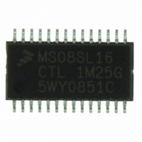
Manufacturer Part Number
MC9S08SL16CTL
Description
MCU 16KB FLASH SLIC 28TSSOP
Manufacturer
Freescale Semiconductor
Series
HCS08r
Datasheet
1.DEMO9S08EL32.pdf
(356 pages)
Specifications of MC9S08SL16CTL
Core Processor
HCS08
Core Size
8-Bit
Speed
40MHz
Connectivity
I²C, LIN, SCI, SPI
Peripherals
LVD, POR, PWM, WDT
Number Of I /o
22
Program Memory Size
16KB (16K x 8)
Program Memory Type
FLASH
Eeprom Size
256 x 8
Ram Size
512 x 8
Voltage - Supply (vcc/vdd)
2.7 V ~ 5.5 V
Data Converters
A/D 16x10b
Oscillator Type
External
Operating Temperature
-40°C ~ 85°C
Package / Case
28-TSSOP
Processor Series
S08SL
Core
HCS08
Data Bus Width
8 bit
Data Ram Size
512 B
Interface Type
I2C/SCI/SPI
Maximum Clock Frequency
40 MHz
Number Of Programmable I/os
22
Number Of Timers
6
Operating Supply Voltage
5.5 V
Maximum Operating Temperature
+ 85 C
Mounting Style
SMD/SMT
3rd Party Development Tools
EWS08
Development Tools By Supplier
DEMO9S08EL32, DEMO9S08EL32AUTO
Minimum Operating Temperature
- 40 C
On-chip Adc
16-ch x 10-bit
Package
28TSSOP
Family Name
HCS08
Maximum Speed
40 MHz
For Use With
DEMO9S08EL32 - BOARD DEMO FOR 9S08 EL MCUDEMO9S08EL32AUTO - DEMO BOARD EL32 AUTO
Lead Free Status / RoHS Status
Lead free / RoHS Compliant
Available stocks
Company
Part Number
Manufacturer
Quantity
Price
Company:

Part Number:
MC9S08SL16CTL
Manufacturer:
Freescale
Quantity:
2 359


12.3.2
SLIC control register 2 (SLCC2) contains bits used to control various features of the SLIC module.
Freescale Semiconductor
TXABRT
SLCIE
IMSG
Field
2
1
0
Reset
W
R
SLIC Control Register 2 (SLCC2)
Transmit Abort Message
0 Normal operation
1 Transmitter aborts current transmission at next byte boundary; TXABRT resets to 0 after the transmission is
SLIC Ignore Message Bit — IMSG cannot be cleared by a write of 0, but is cleared automatically by the SLIC
module after the next BREAK/SYNC symbol pair is validated. After it is set, IMSG will not keep data from being
written to the receive data buffer, which means that the buffers cannot be assumed to contain known valid
message data until the next receive buffer full interrupt. IMSG must not be used in BTM mode. The SLIC
automatically clears the IMSG bit when entering MCU STOP mode or MCU wait mode with SLCWCM bit set.
0 Normal operation1SLIC interrupts (except "No Bus Activity") are suppressed until the next message header
SLIC Interrupt Enable
0 SLIC interrupt sources are disabled
1 SLIC interrupt sources are enabled
successfully aborted TXABRT also resets to 0 upon detection of a bit error.
arrives
0
0
7
= Unimplemented or Reserved
MC9S08EL32 Series and MC9S08SL16 Series Data Sheet, Rev. 3
Table 12-1. SLCC1 Field Descriptions (continued)
6
1
Figure 12-5. SLIC Control Register 2 (SLCC2)
RXFP
0
5
4
0
Description
SLCWCM
0
3
BTM
2
0
0
0
1
SLCE
0
0
193
Related parts for MC9S08SL16CTL
Image
Part Number
Description
Manufacturer
Datasheet
Request
R

Part Number:
Description:
Manufacturer:
Freescale Semiconductor, Inc
Datasheet:
Part Number:
Description:
Manufacturer:
Freescale Semiconductor, Inc
Datasheet:
Part Number:
Description:
Manufacturer:
Freescale Semiconductor, Inc
Datasheet:
Part Number:
Description:
Manufacturer:
Freescale Semiconductor, Inc
Datasheet:
Part Number:
Description:
Manufacturer:
Freescale Semiconductor, Inc
Datasheet:
Part Number:
Description:
Manufacturer:
Freescale Semiconductor, Inc
Datasheet:
Part Number:
Description:
Manufacturer:
Freescale Semiconductor, Inc
Datasheet:
Part Number:
Description:
Manufacturer:
Freescale Semiconductor, Inc
Datasheet:
Part Number:
Description:
Manufacturer:
Freescale Semiconductor, Inc
Datasheet:
Part Number:
Description:
Manufacturer:
Freescale Semiconductor, Inc
Datasheet:
Part Number:
Description:
Manufacturer:
Freescale Semiconductor, Inc
Datasheet:
Part Number:
Description:
Manufacturer:
Freescale Semiconductor, Inc
Datasheet:
Part Number:
Description:
Manufacturer:
Freescale Semiconductor, Inc
Datasheet:
Part Number:
Description:
Manufacturer:
Freescale Semiconductor, Inc
Datasheet:
Part Number:
Description:
Manufacturer:
Freescale Semiconductor, Inc
Datasheet: