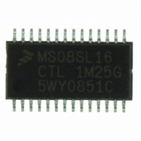
MC9S08SL16CTL Freescale Semiconductor, MC9S08SL16CTL Datasheet - Page 198

MC9S08SL16CTL
Manufacturer Part Number
MC9S08SL16CTL
Description
MCU 16KB FLASH SLIC 28TSSOP
Manufacturer
Freescale Semiconductor
Series
HCS08r
Datasheet
1.DEMO9S08EL32.pdf
(356 pages)
Specifications of MC9S08SL16CTL
Core Processor
HCS08
Core Size
8-Bit
Speed
40MHz
Connectivity
I²C, LIN, SCI, SPI
Peripherals
LVD, POR, PWM, WDT
Number Of I /o
22
Program Memory Size
16KB (16K x 8)
Program Memory Type
FLASH
Eeprom Size
256 x 8
Ram Size
512 x 8
Voltage - Supply (vcc/vdd)
2.7 V ~ 5.5 V
Data Converters
A/D 16x10b
Oscillator Type
External
Operating Temperature
-40°C ~ 85°C
Package / Case
28-TSSOP
Processor Series
S08SL
Core
HCS08
Data Bus Width
8 bit
Data Ram Size
512 B
Interface Type
I2C/SCI/SPI
Maximum Clock Frequency
40 MHz
Number Of Programmable I/os
22
Number Of Timers
6
Operating Supply Voltage
5.5 V
Maximum Operating Temperature
+ 85 C
Mounting Style
SMD/SMT
3rd Party Development Tools
EWS08
Development Tools By Supplier
DEMO9S08EL32, DEMO9S08EL32AUTO
Minimum Operating Temperature
- 40 C
On-chip Adc
16-ch x 10-bit
Package
28TSSOP
Family Name
HCS08
Maximum Speed
40 MHz
For Use With
DEMO9S08EL32 - BOARD DEMO FOR 9S08 EL MCUDEMO9S08EL32AUTO - DEMO BOARD EL32 AUTO
Lead Free Status / RoHS Status
Lead free / RoHS Compliant
Available stocks
Company
Part Number
Manufacturer
Quantity
Price
Company:
Part Number:
MC9S08SL16CTL
Manufacturer:
Freescale
Quantity:
2 359
- Current page: 198 of 356
- Download datasheet (9Mb)
12.3.5.2
When byte transfer mode is enabled (BTM = 1), many of the interrupt sources for the SLCSV no longer
apply, as they are specific to LIN operations.
applicable to BTM operations. The value of the SLCSV for each interrupt source remains the same, as well
as the priority of the interrupt source.
200
•
•
•
•
method was employed for this message frame. Refer to the LIN specification for more details on
the calculations.
Byte Framing Error
This error comes from the standard UART definition for byte encoding and occurs when the STOP
bit is sampled and reads back as a 090. STOP should always read as 1.
Identifier Received Successfully
This interrupt source indicates that a LIN identifier byte has been received with correct parity and
is waiting in the LIN identifier buffer (SLCID). Upon reading this interrupt source from SLCSV,
the user can then decode the identifier in software to determine the nature of the LIN message
frame. To clear this source, SLCID must be read.
Identifier-Parity-Error
A parity error in the identifier (i.e., corrupted identifier) will be flagged. Typical LIN slave
applications do not distinguish between an unknown but valid identifier, and a corrupted identifier.
However, it is mandatory for all slave nodes to evaluate in case of a known identifier all eight bits
of the ID-Field and distinguish between a known and a corrupted identifier. The received identifier
value is reported in SLCID so that the user software can choose to acknowledge or ignore the parity
error message. Once the ID parity error has been detected, the SLIC will begin looking for another
LIN header and will not receive message data, even if it appears on the bus.
Wakeup
The wakeup interrupt source indicates that the SLIC module has entered SLIC run mode from
SLIC stop mode.
Byte Transfer Mode Operation
A byte framing error can also be an indication that the number of data bytes
received in a LIN message frame does not match the value written to the
SLCDLC register. See
for more details.
SLCSV
0x0C
0x1C
0x00
0x14
0x18
MC9S08EL32 Series and MC9S08SL16 Series Data Sheet, Rev. 3
Table 12-9. Interrupt Sources Summary (BTM = 1)
I3
0
0
0
0
0
I2
0
0
1
1
1
Section 12.6.7, “Handling LIN Message
I1
0
1
0
1
1
I0
0
1
1
0
1
Table 12-9
NOTE
TX Message Buffer Empty
Receiver Buffer Overrun
I
No Interrupts Pending
RX Data Buffer Full
Interrupt Source
shows those interrupt sources which are
No Errors
Bit-Error
Headers,”
0 (Lowest)
Priority
3
5
6
7
Freescale Semiconductor
Related parts for MC9S08SL16CTL
Image
Part Number
Description
Manufacturer
Datasheet
Request
R
Part Number:
Description:
Manufacturer:
Freescale Semiconductor, Inc
Datasheet:
Part Number:
Description:
Manufacturer:
Freescale Semiconductor, Inc
Datasheet:
Part Number:
Description:
Manufacturer:
Freescale Semiconductor, Inc
Datasheet:
Part Number:
Description:
Manufacturer:
Freescale Semiconductor, Inc
Datasheet:
Part Number:
Description:
Manufacturer:
Freescale Semiconductor, Inc
Datasheet:
Part Number:
Description:
Manufacturer:
Freescale Semiconductor, Inc
Datasheet:
Part Number:
Description:
Manufacturer:
Freescale Semiconductor, Inc
Datasheet:
Part Number:
Description:
Manufacturer:
Freescale Semiconductor, Inc
Datasheet:
Part Number:
Description:
Manufacturer:
Freescale Semiconductor, Inc
Datasheet:
Part Number:
Description:
Manufacturer:
Freescale Semiconductor, Inc
Datasheet:
Part Number:
Description:
Manufacturer:
Freescale Semiconductor, Inc
Datasheet:
Part Number:
Description:
Manufacturer:
Freescale Semiconductor, Inc
Datasheet:
Part Number:
Description:
Manufacturer:
Freescale Semiconductor, Inc
Datasheet:
Part Number:
Description:
Manufacturer:
Freescale Semiconductor, Inc
Datasheet:
Part Number:
Description:
Manufacturer:
Freescale Semiconductor, Inc
Datasheet:


