DF2210CUNP24V Renesas Electronics America, DF2210CUNP24V Datasheet - Page 655
DF2210CUNP24V
Manufacturer Part Number
DF2210CUNP24V
Description
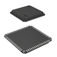
MCU 16BIT FLASH 3V 32K 64-QFN
Manufacturer
Renesas Electronics America
Series
H8® H8S/2200r
Datasheet
1.DF2218UTF24V.pdf
(758 pages)
Specifications of DF2210CUNP24V
Core Processor
H8S/2000
Core Size
16-Bit
Speed
24MHz
Connectivity
SCI, SmartCard, USB
Peripherals
DMA, POR, PWM, WDT
Number Of I /o
37
Program Memory Size
32KB (32K x 8)
Program Memory Type
FLASH
Ram Size
4K x 8
Voltage - Supply (vcc/vdd)
2.7 V ~ 3.6 V
Data Converters
A/D 6x10b
Oscillator Type
External
Operating Temperature
-20°C ~ 75°C
Package / Case
64-QFN
Lead Free Status / RoHS Status
Lead free / RoHS Compliant
Eeprom Size
-
Available stocks
Company
Part Number
Manufacturer
Quantity
Price
Company:

Part Number:
DF2210CUNP24V
Manufacturer:
Renesas Electronics America
Quantity:
135


Note: * When watch mode or subactive mode is entered, set high-speed mode.
Bit
3
2
1
0
Bit Name Initial Value R/W
RFCUT
⎯
STC1
STC0
0
0
0
0
R/W
R/W
R/W
R/W
Description
Built-in Feedback Resistor Control
Selects whether the oscillator’s built-in feedback resistor
and duty adjustment circuit are used with external clock
input. This bit should not be accessed when a crystal
oscillator is used.
After this bit is set when using external clock input, a
transition should initially be made to software standby
mode. Switching between use and non-use of the
oscillator’s built-in feedback resistor and duty adjustment
circuit is performed when the transition is made to software
standby mode.
0: Main clock oscillator’s built-in feedback resistor and duty
1: Main clock oscillator’s built-in feedback resistor and duty
Reserved
This bit can be read from or written to, but the write value
should always 0.
Frequency Multiplication Factor
Specify the frequency multiplication factor of the PLL circuit
incorporated into the evaluation chip. The specified
frequency multiplication factor is valid after a transition to
software standby mode.
With this LSI, the STC1 and STC0 bits must both be set to
1. After a reset, the STC1 and STC0 bits are both cleared
to 0, and so they must be set to 1.
00: × 1
01: × 2 (Setting prohibited)
10: × 4 (Setting prohibited)
11: PLL is bypassed
adjustment circuit are used
adjustment circuit are not used
Rev.7.00 Dec. 24, 2008 Page 599 of 698
REJ09B0074-0700
Related parts for DF2210CUNP24V
Image
Part Number
Description
Manufacturer
Datasheet
Request
R

Part Number:
Description:
KIT STARTER FOR M16C/29
Manufacturer:
Renesas Electronics America
Datasheet:

Part Number:
Description:
KIT STARTER FOR R8C/2D
Manufacturer:
Renesas Electronics America
Datasheet:

Part Number:
Description:
R0K33062P STARTER KIT
Manufacturer:
Renesas Electronics America
Datasheet:

Part Number:
Description:
KIT STARTER FOR R8C/23 E8A
Manufacturer:
Renesas Electronics America
Datasheet:

Part Number:
Description:
KIT STARTER FOR R8C/25
Manufacturer:
Renesas Electronics America
Datasheet:

Part Number:
Description:
KIT STARTER H8S2456 SHARPE DSPLY
Manufacturer:
Renesas Electronics America
Datasheet:

Part Number:
Description:
KIT STARTER FOR R8C38C
Manufacturer:
Renesas Electronics America
Datasheet:

Part Number:
Description:
KIT STARTER FOR R8C35C
Manufacturer:
Renesas Electronics America
Datasheet:

Part Number:
Description:
KIT STARTER FOR R8CL3AC+LCD APPS
Manufacturer:
Renesas Electronics America
Datasheet:
Part Number:
Description:
KIT STARTER FOR RX610
Manufacturer:
Renesas Electronics America
Datasheet:

Part Number:
Description:
KIT STARTER FOR R32C/118
Manufacturer:
Renesas Electronics America
Datasheet:

Part Number:
Description:
KIT DEV RSK-R8C/26-29
Manufacturer:
Renesas Electronics America
Datasheet:

Part Number:
Description:
KIT STARTER FOR SH7124
Manufacturer:
Renesas Electronics America
Datasheet:

Part Number:
Description:
KIT STARTER FOR H8SX/1622
Manufacturer:
Renesas Electronics America
Datasheet:

Part Number:
Description:
KIT DEV FOR SH7203
Manufacturer:
Renesas Electronics America
Datasheet: