MC908GT16CBE Freescale Semiconductor, MC908GT16CBE Datasheet - Page 114
MC908GT16CBE
Manufacturer Part Number
MC908GT16CBE
Description
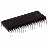
IC MCU 16K FLASH 8MHZ SPI 42SDIP
Manufacturer
Freescale Semiconductor
Series
HC08r
Datasheet
1.MC908GT8CFBE.pdf
(292 pages)
Specifications of MC908GT16CBE
Core Processor
HC08
Core Size
8-Bit
Speed
8MHz
Connectivity
SCI, SPI
Peripherals
LVD, POR, PWM
Number Of I /o
36
Program Memory Size
16KB (16K x 8)
Program Memory Type
FLASH
Ram Size
512 x 8
Voltage - Supply (vcc/vdd)
2.7 V ~ 5.5 V
Data Converters
A/D 8x8b
Oscillator Type
Internal
Operating Temperature
-40°C ~ 85°C
Package / Case
42-DIP (0.600", 15.24mm)
Controller Family/series
HC08
No. Of I/o's
34
Ram Memory Size
512Byte
Cpu Speed
8MHz
No. Of Timers
2
Embedded Interface Type
I2C, SCI, SPI
Rohs Compliant
Yes
Processor Series
HC08GT
Core
HC08
Data Bus Width
8 bit
Data Ram Size
512 B
Interface Type
SCI, SPI
Maximum Clock Frequency
8 MHz
Number Of Programmable I/os
30
Number Of Timers
4
Operating Supply Voltage
0 V to 5 V
Maximum Operating Temperature
+ 85 C
Mounting Style
Through Hole
Development Tools By Supplier
FSICEBASE, DEMO908GZ60E, M68CBL05CE, M68EML08GPGTE
Minimum Operating Temperature
- 40 C
On-chip Adc
8 bit, 8 Channel
Package
42SPDIP
Family Name
HC08
Maximum Speed
8 MHz
Lead Free Status / RoHS Status
Lead free / RoHS Compliant
Eeprom Size
-
Lead Free Status / Rohs Status
Details


Low-Voltage Inhibit (LVI)
LVISTOP, LVIPWRD, LVI5OR3, and LVIRSTD are in the configuration register (CONFIG1). See
4-2. Configuration Register 1 (CONFIG1)
occurs, the MCU remains in reset until V
reset. See
LVI. The output of the comparator controls the state of the LVIOUT flag in the LVI status register (LVISR).
An LVI reset also drives the RST pin low to provide low-voltage protection to external peripheral devices.
10.3.1 Polled LVI Operation
In applications that can operate at V
the LVIOUT bit. In the configuration register, the LVIPWRD bit must be at 0 to enable the LVI module, and
the LVIRSTD bit must be at 1 to disable LVI resets.
10.3.2 Forced Reset Operation
In applications that require V
module to reset the MCU when V
LVIPWRD and LVIRSTD bits must be at 0 to enable the LVI module and to enable LVI resets.
10.3.3 Voltage Hysteresis Protection
Once the LVI has triggered (by having V
V
114
$FE0C
Addr.
DD
rises above the rising trip point voltage, V
15.3.2.5 Low-Voltage Inhibit (LVI) Reset
Register Name
LVI Status Register
See page 115.
FROM CONFIG1
MC68HC908GT16 • MC68HC908GT8 • MC68HC08GT16 Data Sheet, Rev. 5.0
(LVISR)
DETECTOR
LOW V
LVI5OR3
V
DD
DD
Reset:
Read:
Write:
DD
Figure 10-1. LVI Module Block Diagram
Figure 10-2. LVI I/O Register Summary
to remain above the V
V
V
DD
DD
DD
FROM CONFIG
LVIOUT
> LVI
≤ LVI
DD
Bit 7
LVIPWRD
falls below the V
0
Trip
Trip
levels below the V
DD
DD
= 0
= 1
for details of the LVI’s configuration bits. Once an LVI reset
= Unimplemented
fall below V
rises above a voltage, V
6
0
0
TRIPR
LVIOUT
for details of the interaction between the SIM and the
. This prevents a condition in which the MCU is
TRIPF
TRIPF
TRIPF
STOP INSTRUCTION
5
0
0
FROM CONFIG1
TRIPF
level. In the configuration register, the
LVIRSTD
), the LVI will maintain a reset condition until
level, enabling LVI resets allows the LVI
level, software can monitor V
4
0
0
TRIPR
3
0
0
, which causes the MCU to exit
FROM CONFIG1
LVISTOP
LVI RESET
2
0
0
Freescale Semiconductor
1
0
0
DD
by polling
Figure
Bit 0
0
0
Related parts for MC908GT16CBE
Image
Part Number
Description
Manufacturer
Datasheet
Request
R

Part Number:
Description:
Manufacturer:
Freescale Semiconductor, Inc
Datasheet:
Part Number:
Description:
Manufacturer:
Freescale Semiconductor, Inc
Datasheet:
Part Number:
Description:
Manufacturer:
Freescale Semiconductor, Inc
Datasheet:
Part Number:
Description:
Manufacturer:
Freescale Semiconductor, Inc
Datasheet:
Part Number:
Description:
Manufacturer:
Freescale Semiconductor, Inc
Datasheet:
Part Number:
Description:
Manufacturer:
Freescale Semiconductor, Inc
Datasheet:
Part Number:
Description:
Manufacturer:
Freescale Semiconductor, Inc
Datasheet:
Part Number:
Description:
Manufacturer:
Freescale Semiconductor, Inc
Datasheet:
Part Number:
Description:
Manufacturer:
Freescale Semiconductor, Inc
Datasheet:
Part Number:
Description:
Manufacturer:
Freescale Semiconductor, Inc
Datasheet:
Part Number:
Description:
Manufacturer:
Freescale Semiconductor, Inc
Datasheet:
Part Number:
Description:
Manufacturer:
Freescale Semiconductor, Inc
Datasheet:
Part Number:
Description:
Manufacturer:
Freescale Semiconductor, Inc
Datasheet:
Part Number:
Description:
Manufacturer:
Freescale Semiconductor, Inc
Datasheet:
Part Number:
Description:
Manufacturer:
Freescale Semiconductor, Inc
Datasheet: