MC908GT16CBE Freescale Semiconductor, MC908GT16CBE Datasheet - Page 161
MC908GT16CBE
Manufacturer Part Number
MC908GT16CBE
Description
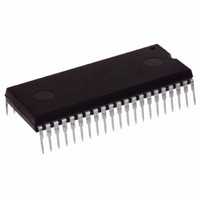
IC MCU 16K FLASH 8MHZ SPI 42SDIP
Manufacturer
Freescale Semiconductor
Series
HC08r
Datasheet
1.MC908GT8CFBE.pdf
(292 pages)
Specifications of MC908GT16CBE
Core Processor
HC08
Core Size
8-Bit
Speed
8MHz
Connectivity
SCI, SPI
Peripherals
LVD, POR, PWM
Number Of I /o
36
Program Memory Size
16KB (16K x 8)
Program Memory Type
FLASH
Ram Size
512 x 8
Voltage - Supply (vcc/vdd)
2.7 V ~ 5.5 V
Data Converters
A/D 8x8b
Oscillator Type
Internal
Operating Temperature
-40°C ~ 85°C
Package / Case
42-DIP (0.600", 15.24mm)
Controller Family/series
HC08
No. Of I/o's
34
Ram Memory Size
512Byte
Cpu Speed
8MHz
No. Of Timers
2
Embedded Interface Type
I2C, SCI, SPI
Rohs Compliant
Yes
Processor Series
HC08GT
Core
HC08
Data Bus Width
8 bit
Data Ram Size
512 B
Interface Type
SCI, SPI
Maximum Clock Frequency
8 MHz
Number Of Programmable I/os
30
Number Of Timers
4
Operating Supply Voltage
0 V to 5 V
Maximum Operating Temperature
+ 85 C
Mounting Style
Through Hole
Development Tools By Supplier
FSICEBASE, DEMO908GZ60E, M68CBL05CE, M68EML08GPGTE
Minimum Operating Temperature
- 40 C
On-chip Adc
8 bit, 8 Channel
Package
42SPDIP
Family Name
HC08
Maximum Speed
8 MHz
Lead Free Status / RoHS Status
Lead free / RoHS Compliant
Eeprom Size
-
Lead Free Status / Rohs Status
Details


14.4.3.7 Receiver Interrupts
These sources can generate CPU interrupt requests from the ESCI receiver:
14.4.3.8 Error Interrupts
These receiver error flags in SCS1 can generate CPU interrupt requests:
14.5 Low-Power Modes
The WAIT and STOP instructions put the MCU in low power-consumption standby modes.
14.5.1 Wait Mode
The ESCI module remains active in wait mode. Any enabled CPU interrupt request from the ESCI module
can bring the MCU out of wait mode.
If ESCI module functions are not required during wait mode, reduce power consumption by disabling the
module before executing the WAIT instruction.
14.5.2 Stop Mode
The ESCI module is inactive in stop mode. The STOP instruction does not affect ESCI register states.
ESCI module operation resumes after the MCU exits stop mode.
Because the internal clock is inactive during stop mode, entering stop mode during an ESCI transmission
or reception results in invalid data.
Freescale Semiconductor
•
•
•
•
•
•
ESCI receiver full (SCRF) — The SCRF bit in SCS1 indicates that the receive shift register has
transferred a character to the SCDR. SCRF can generate a receiver CPU interrupt request. Setting
the ESCI receive interrupt enable bit, SCRIE, in SCC2 enables the SCRF bit to generate receiver
CPU interrupts.
Idle input (IDLE) — The IDLE bit in SCS1 indicates that 10 or 11 consecutive 1s shifted in from the
RxD pin. The idle line interrupt enable bit, ILIE, in SCC2 enables the IDLE bit to generate CPU
interrupt requests.
Receiver overrun (OR) — The OR bit indicates that the receive shift register shifted in a new
character before the previous character was read from the SCDR. The previous character remains
in the SCDR, and the new character is lost. The overrun interrupt enable bit, ORIE, in SCC3
enables OR to generate ESCI error CPU interrupt requests.
Noise flag (NF) — The NF bit is set when the ESCI detects noise on incoming data or break
characters, including start, data, and stop bits. The noise error interrupt enable bit, NEIE, in SCC3
enables NF to generate ESCI error CPU interrupt requests.
Framing error (FE) — The FE bit in SCS1 is set when a 0 occurs where the receiver expects a stop
bit. The framing error interrupt enable bit, FEIE, in SCC3 enables FE to generate ESCI error CPU
interrupt requests.
Parity error (PE) — The PE bit in SCS1 is set when the ESCI detects a parity error in incoming
data. The parity error interrupt enable bit, PEIE, in SCC3 enables PE to generate ESCI error CPU
interrupt requests.
MC68HC908GT16 • MC68HC908GT8 • MC68HC08GT16 Data Sheet, Rev. 5.0
Low-Power Modes
161
Related parts for MC908GT16CBE
Image
Part Number
Description
Manufacturer
Datasheet
Request
R

Part Number:
Description:
Manufacturer:
Freescale Semiconductor, Inc
Datasheet:
Part Number:
Description:
Manufacturer:
Freescale Semiconductor, Inc
Datasheet:
Part Number:
Description:
Manufacturer:
Freescale Semiconductor, Inc
Datasheet:
Part Number:
Description:
Manufacturer:
Freescale Semiconductor, Inc
Datasheet:
Part Number:
Description:
Manufacturer:
Freescale Semiconductor, Inc
Datasheet:
Part Number:
Description:
Manufacturer:
Freescale Semiconductor, Inc
Datasheet:
Part Number:
Description:
Manufacturer:
Freescale Semiconductor, Inc
Datasheet:
Part Number:
Description:
Manufacturer:
Freescale Semiconductor, Inc
Datasheet:
Part Number:
Description:
Manufacturer:
Freescale Semiconductor, Inc
Datasheet:
Part Number:
Description:
Manufacturer:
Freescale Semiconductor, Inc
Datasheet:
Part Number:
Description:
Manufacturer:
Freescale Semiconductor, Inc
Datasheet:
Part Number:
Description:
Manufacturer:
Freescale Semiconductor, Inc
Datasheet:
Part Number:
Description:
Manufacturer:
Freescale Semiconductor, Inc
Datasheet:
Part Number:
Description:
Manufacturer:
Freescale Semiconductor, Inc
Datasheet:
Part Number:
Description:
Manufacturer:
Freescale Semiconductor, Inc
Datasheet: