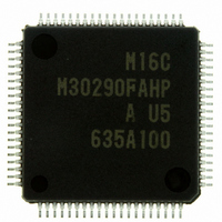
M30290FAHP#U5A Renesas Electronics America, M30290FAHP#U5A Datasheet - Page 183

M30290FAHP#U5A
Manufacturer Part Number
M30290FAHP#U5A
Description
IC M16C/29 MCU FLASH 96K 80LQFP
Manufacturer
Renesas Electronics America
Series
M16C™ M16C/Tiny/29r
Datasheet
1.M30291FCHPU5A.pdf
(501 pages)
Specifications of M30290FAHP#U5A
Core Processor
M16C/60
Core Size
16-Bit
Speed
20MHz
Connectivity
CAN, I²C, IEBus, SIO, UART/USART
Peripherals
DMA, POR, PWM, Voltage Detect, WDT
Number Of I /o
71
Program Memory Size
96KB (96K x 8)
Program Memory Type
FLASH
Ram Size
8K x 8
Voltage - Supply (vcc/vdd)
2.7 V ~ 5.5 V
Data Converters
A/D 27x10b
Oscillator Type
Internal
Operating Temperature
-20°C ~ 85°C
Package / Case
80-LQFP
For Use With
R0K330290S000BE - KIT EVAL STARTER FOR M16C/29M30290T2-CPE - EMULATOR COMPACT M16C/26A/28/29M30290T2-CPE-HP - EMULATOR COMPACT FOR M16C/TINY
Lead Free Status / RoHS Status
Lead free / RoHS Compliant
Eeprom Size
-
Available stocks
Company
Part Number
Manufacturer
Quantity
Price
Part Number:
M30290FAHP#U5AM30290FAHP#D3
Manufacturer:
Renesas Electronics America
Quantity:
10 000
Part Number:
M30290FAHP#U5AM30290FAHP#U3A
Manufacturer:
Renesas Electronics America
Quantity:
135
Part Number:
M30290FAHP#U5AM30290FAHP#U3A
Manufacturer:
Renesas Electronics America
Quantity:
10 000
- Current page: 183 of 501
- Download datasheet (5Mb)
R
R
M
13.4 Time Measurement Function
e
E
1
. v
J
6
Table 13.5 Time Measurement Function Specifications
0
Measurement channel
Selecting trigger input polarity
Measurement start condition
Measurement stop condition
Time measurement timing
Interrupt request generation timing
INPC1j pin function
Selectable function
NOTE:
In synchronization with an external trigger input, the value of the base timer is stored into the G1TMj
register (j=0 to 7). Table 13.5 shows specifications of the time measurement function. Table 13.6 shows
register settings associated with the time measurement function. Figures 13.19 and 13.20 display opera-
tional timing of the time measurement function. Figure 13.21 shows operational timing of the prescaler
function and the gate function.
1
C
9
1 .
B
2 /
1. The INPC1
0
2
9
1
M
0
G
1
r a
0 -
o r
3 .
1
u
, 0
1
p
Item
2
2
0
0
0
7
to INPC1
(1)
page 157
7
pins
f o
4
5
Channels 0 to 7
Rising edge, falling edge, both edges of the INPC1j pin
The IFEj bit in the G1FE register should be set to 1 (channels j function
enabled) when the FSCj bit (j=0 to 7) in the G1FS register is set to 1 (time
measurement function selected).
The IFEj bit should be set to 0 (channel j function disabled)
•No prescaler : every time a trigger signal is applied
•Prescaler (for channel 6 and channel 7):
The G1IRi bit (i=0 to 7) in the interrupt request register (See Figure 13.9) is
set to 1 at time measurement timing
Trigger input pin
• Digital filter function
• Prescaler function (for channel 6 and channel 7)
• Gate function (for channel 6 and channel 7)
• Digital Debounce function (for channel7)
8
every
The digital filter samples a trigger input signal level every f
cycles and passes pulse signal matching trigger input signal level three
times
Time measurement is executed every
trigger signal is applied
After time measurement by the first trigger input, trigger input cannot be
accepted. However, while the GOC bit in the G1TMCRk register is set to 1
(gate cleared by matching the base timer with the G1POp register (p=4
when k=6, p=5 when k=7)), trigger input can be accepted again by
matching the base timer value with the G1POp register setting
See 13.6.2 Digital Debounce Function for P1
Digital Debounce Function for details
G1TPR
k (k=6,7)
register value +1
Specification
times a trigger signal is applied
G1TPRk register value +1
7
/INT5/INPC17 and 19.6
________
(1)
1
, f
2
or f
times a
BT1
Related parts for M30290FAHP#U5A
Image
Part Number
Description
Manufacturer
Datasheet
Request
R

Part Number:
Description:
KIT STARTER FOR M16C/29
Manufacturer:
Renesas Electronics America
Datasheet:

Part Number:
Description:
KIT STARTER FOR R8C/2D
Manufacturer:
Renesas Electronics America
Datasheet:

Part Number:
Description:
R0K33062P STARTER KIT
Manufacturer:
Renesas Electronics America
Datasheet:

Part Number:
Description:
KIT STARTER FOR R8C/23 E8A
Manufacturer:
Renesas Electronics America
Datasheet:

Part Number:
Description:
KIT STARTER FOR R8C/25
Manufacturer:
Renesas Electronics America
Datasheet:

Part Number:
Description:
KIT STARTER H8S2456 SHARPE DSPLY
Manufacturer:
Renesas Electronics America
Datasheet:

Part Number:
Description:
KIT STARTER FOR R8C38C
Manufacturer:
Renesas Electronics America
Datasheet:

Part Number:
Description:
KIT STARTER FOR R8C35C
Manufacturer:
Renesas Electronics America
Datasheet:

Part Number:
Description:
KIT STARTER FOR R8CL3AC+LCD APPS
Manufacturer:
Renesas Electronics America
Datasheet:

Part Number:
Description:
KIT STARTER FOR RX610
Manufacturer:
Renesas Electronics America
Datasheet:

Part Number:
Description:
KIT STARTER FOR R32C/118
Manufacturer:
Renesas Electronics America
Datasheet:

Part Number:
Description:
KIT DEV RSK-R8C/26-29
Manufacturer:
Renesas Electronics America
Datasheet:

Part Number:
Description:
KIT STARTER FOR SH7124
Manufacturer:
Renesas Electronics America
Datasheet:

Part Number:
Description:
KIT STARTER FOR H8SX/1622
Manufacturer:
Renesas Electronics America
Datasheet:

Part Number:
Description:
KIT DEV FOR SH7203
Manufacturer:
Renesas Electronics America
Datasheet:


