D12350F20IV Renesas Electronics America, D12350F20IV Datasheet - Page 30
D12350F20IV
Manufacturer Part Number
D12350F20IV
Description
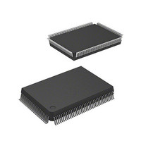
IC H8S/2350 MCU 4.5/5.5V 0+K I-T
Manufacturer
Renesas Electronics America
Series
H8® H8S/2300r
Specifications of D12350F20IV
Core Processor
H8S/2000
Core Size
16-Bit
Speed
20MHz
Connectivity
SCI, SmartCard
Peripherals
DMA, POR, PWM, WDT
Number Of I /o
87
Program Memory Type
ROMless
Ram Size
2K x 8
Voltage - Supply (vcc/vdd)
2.7 V ~ 5.5 V
Data Converters
A/D 8x10b; D/A 2x8b
Oscillator Type
Internal
Operating Temperature
-40°C ~ 85°C
Package / Case
128-QFP
Lead Free Status / RoHS Status
Lead free / RoHS Compliant
Eeprom Size
-
Program Memory Size
-
Available stocks
Company
Part Number
Manufacturer
Quantity
Price
Company:

Part Number:
D12350F20IV
Manufacturer:
INF
Quantity:
4 834


11.3 Operation........................................................................................................................... 520
11.4 Usage Notes ...................................................................................................................... 529
Section 12 Watchdog Timer (WDT)
12.1 Overview........................................................................................................................... 531
12.2 Register Descriptions ........................................................................................................ 534
12.3 Operation........................................................................................................................... 540
12.4 Interrupts ........................................................................................................................... 543
12.5 Usage Notes ...................................................................................................................... 543
Section 13 Serial Communication Interface (SCI)
13.1 Overview........................................................................................................................... 545
13.2 Register Descriptions ........................................................................................................ 550
Rev. 3.00 Sep 15, 2006 page xxviii of xxxiv
11.2.9 Module Stop Control Register (MSTPCR) .......................................................... 519
11.3.1 Overview.............................................................................................................. 520
11.3.2 Output Timing...................................................................................................... 521
11.3.3 Normal Pulse Output............................................................................................ 522
11.3.4 Non-Overlapping Pulse Output............................................................................ 524
11.3.5 Inverted Pulse Output........................................................................................... 527
11.3.6 Pulse Output Triggered by Input Capture ............................................................ 528
12.1.1 Features................................................................................................................ 531
12.1.2 Block Diagram ..................................................................................................... 532
12.1.3 Pin Configuration................................................................................................. 533
12.1.4 Register Configuration ......................................................................................... 533
12.2.1 Timer Counter (TCNT)........................................................................................ 534
12.2.2 Timer Control/Status Register (TCSR) ................................................................ 534
12.2.3 Reset Control/Status Register (RSTCSR) ............................................................ 536
12.2.4 Notes on Register Access..................................................................................... 538
12.3.1 Watchdog Timer Operation ................................................................................. 540
12.3.2 Interval Timer Operation ..................................................................................... 541
12.3.3 Timing of Setting Overflow Flag (OVF).............................................................. 541
12.3.4 Timing of Setting of Watchdog Timer Overflow Flag (WOVF).......................... 542
12.5.1 Contention between Timer Counter (TCNT) Write and Increment ..................... 543
12.5.2 Changing Value of CKS2 to CKS0 ...................................................................... 544
12.5.3 Switching between Watchdog Timer Mode and Interval Timer Mode ................ 544
12.5.4 System Reset by WDTOVF Signal ...................................................................... 544
12.5.5 Internal Reset in Watchdog Timer Mode ............................................................. 544
13.1.1 Features................................................................................................................ 545
13.1.2 Block Diagram ..................................................................................................... 547
13.1.3 Pin Configuration................................................................................................. 548
13.1.4 Register Configuration ......................................................................................... 549
.............................................................................. 531
..................................................... 545
Related parts for D12350F20IV
Image
Part Number
Description
Manufacturer
Datasheet
Request
R

Part Number:
Description:
KIT STARTER FOR M16C/29
Manufacturer:
Renesas Electronics America
Datasheet:

Part Number:
Description:
KIT STARTER FOR R8C/2D
Manufacturer:
Renesas Electronics America
Datasheet:

Part Number:
Description:
R0K33062P STARTER KIT
Manufacturer:
Renesas Electronics America
Datasheet:

Part Number:
Description:
KIT STARTER FOR R8C/23 E8A
Manufacturer:
Renesas Electronics America
Datasheet:

Part Number:
Description:
KIT STARTER FOR R8C/25
Manufacturer:
Renesas Electronics America
Datasheet:

Part Number:
Description:
KIT STARTER H8S2456 SHARPE DSPLY
Manufacturer:
Renesas Electronics America
Datasheet:

Part Number:
Description:
KIT STARTER FOR R8C38C
Manufacturer:
Renesas Electronics America
Datasheet:

Part Number:
Description:
KIT STARTER FOR R8C35C
Manufacturer:
Renesas Electronics America
Datasheet:

Part Number:
Description:
KIT STARTER FOR R8CL3AC+LCD APPS
Manufacturer:
Renesas Electronics America
Datasheet:
Part Number:
Description:
KIT STARTER FOR RX610
Manufacturer:
Renesas Electronics America
Datasheet:

Part Number:
Description:
KIT STARTER FOR R32C/118
Manufacturer:
Renesas Electronics America
Datasheet:

Part Number:
Description:
KIT DEV RSK-R8C/26-29
Manufacturer:
Renesas Electronics America
Datasheet:

Part Number:
Description:
KIT STARTER FOR SH7124
Manufacturer:
Renesas Electronics America
Datasheet:

Part Number:
Description:
KIT STARTER FOR H8SX/1622
Manufacturer:
Renesas Electronics America
Datasheet:

Part Number:
Description:
KIT DEV FOR SH7203
Manufacturer:
Renesas Electronics America
Datasheet: