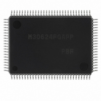
M30624FGAFP#U3 Renesas Electronics America, M30624FGAFP#U3 Datasheet - Page 451

M30624FGAFP#U3
Manufacturer Part Number
M30624FGAFP#U3
Description
IC M16C MCU FLASH 100QFP
Manufacturer
Renesas Electronics America
Series
M16C™ M16C/60r
Datasheets
1.M30622SAFPU5.pdf
(277 pages)
2.M30622SAFPU5.pdf
(617 pages)
3.M30622SAFPU5.pdf
(308 pages)
Specifications of M30624FGAFP#U3
Core Processor
M16C/60
Core Size
16-Bit
Speed
16MHz
Connectivity
SIO, UART/USART
Peripherals
DMA, PWM, WDT
Number Of I /o
85
Program Memory Size
256KB (256K x 8)
Program Memory Type
FLASH
Ram Size
20K x 8
Voltage - Supply (vcc/vdd)
4.2 V ~ 5.5 V
Data Converters
A/D 10x10b, D/A 2x8b
Oscillator Type
Internal
Operating Temperature
-40°C ~ 85°C
Package / Case
100-QFP
For Use With
867-1000 - KIT QUICK START RENESAS 62PM3062PT3-CPE-3 - EMULATOR COMPACT M16C/62P/30P
Lead Free Status / RoHS Status
Lead free / RoHS Compliant
Eeprom Size
-
Available stocks
Company
Part Number
Manufacturer
Quantity
Price
Part Number:
M30624FGAFP#U3M30624FGAFP#D3
Manufacturer:
Renesas Electronics America
Quantity:
10 000
Part Number:
M30624FGAFP#U3M30624FGAFP#D5
Manufacturer:
Renesas Electronics America
Quantity:
10 000
- Current page: 451 of 617
- Download datasheet (9Mb)
A-D Converter
2-132
Figure 2.7.22. Use of capacitors to reduce noise
2.7.10 Precautions for A-D Converter
(1) Write to each bit (except bit 6) of A-D control register 0, to each bit of A-D control register 1,
(2) To reduce conversion error due to noise, connect a voltage to the AVcc pin and to the Vref pin from
(3) Set the direction register of the following ports to input: the port corresponding to a pin to be
(4) In using a key-input interrupt, none of the 4 pins (AN
(5) If using the A-D converter with Vcc = 2.7V to 4.0 V:
(6) Rewrite to analog input pin select bits after changing A-D operation mode.
(7) When using the one-shot or single sweep mode
(8) When using the repeat mode or repeat sweep mode 0 or 1
(9) Use AD under 10 MHz. When X
Microcomputer
and to bit 0 of A-D control register 2 when A-D conversion is stopped (before a trigger occurs).
In particular, when the Vref connection bit is changed from 0 to 1, start A-D conversion after
an elapse of 1 s or longer.
an independent source. It is recommended to connect a capacitor between the AVss pin and the
AVcc pin, between the AVss pin and the Vref pin, and between the AVss pin and the analog input
pin (ANi). Figure 2.7.22 shows the an example of connecting the capacitors to these pins.
used as an analog input pin and external trigger input pin (P9
conversion port (if the A-D input voltage goes to “L” level, a key-input interrupt occurs).
Use only a divided frequency for f
Select without the Sample & Hold feature.
Select 8-bit mode.
Confirm that A-D conversion is complete before reading the A-D register.
(Note: When A-D conversion interrupt request bit is set, it shows that A-D conversion is completed.)
Use the undivided main clock as the internal CPU clock.
AV
AV
V
V
REF
AN
CC
CC
SS
i
C1
C3
C2
Note
Note
IN
is over 10 MHz, divide it.
1:
2:
AD
C1 0.47 µF, C2 0.47 µF, C3 100 pF
(for reference)
Use thick and shortest possible wiring
to connect capacitors.
(undivided f
AD
4
through AN
is not allowed).
SINGLE-CHIP 16-BIT CMOS MICROCOMPUTER
7
).
7
) can be used as an A-D
M16C / 62A Group
Mitsubishi microcomputers
Related parts for M30624FGAFP#U3
Image
Part Number
Description
Manufacturer
Datasheet
Request
R

Part Number:
Description:
KIT STARTER FOR M16C/29
Manufacturer:
Renesas Electronics America
Datasheet:

Part Number:
Description:
KIT STARTER FOR R8C/2D
Manufacturer:
Renesas Electronics America
Datasheet:

Part Number:
Description:
R0K33062P STARTER KIT
Manufacturer:
Renesas Electronics America
Datasheet:

Part Number:
Description:
KIT STARTER FOR R8C/23 E8A
Manufacturer:
Renesas Electronics America
Datasheet:

Part Number:
Description:
KIT STARTER FOR R8C/25
Manufacturer:
Renesas Electronics America
Datasheet:

Part Number:
Description:
KIT STARTER H8S2456 SHARPE DSPLY
Manufacturer:
Renesas Electronics America
Datasheet:

Part Number:
Description:
KIT STARTER FOR R8C38C
Manufacturer:
Renesas Electronics America
Datasheet:

Part Number:
Description:
KIT STARTER FOR R8C35C
Manufacturer:
Renesas Electronics America
Datasheet:

Part Number:
Description:
KIT STARTER FOR R8CL3AC+LCD APPS
Manufacturer:
Renesas Electronics America
Datasheet:

Part Number:
Description:
KIT STARTER FOR RX610
Manufacturer:
Renesas Electronics America
Datasheet:

Part Number:
Description:
KIT STARTER FOR R32C/118
Manufacturer:
Renesas Electronics America
Datasheet:

Part Number:
Description:
KIT DEV RSK-R8C/26-29
Manufacturer:
Renesas Electronics America
Datasheet:

Part Number:
Description:
KIT STARTER FOR SH7124
Manufacturer:
Renesas Electronics America
Datasheet:

Part Number:
Description:
KIT STARTER FOR H8SX/1622
Manufacturer:
Renesas Electronics America
Datasheet:

Part Number:
Description:
KIT DEV FOR SH7203
Manufacturer:
Renesas Electronics America
Datasheet:


