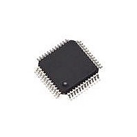
SAF-XC886CLM-8FFI 5V AC Infineon Technologies, SAF-XC886CLM-8FFI 5V AC Datasheet - Page 140

SAF-XC886CLM-8FFI 5V AC
Manufacturer Part Number
SAF-XC886CLM-8FFI 5V AC
Description
IC MCU 8BIT FLASH TQFP-48
Manufacturer
Infineon Technologies
Series
XC8xxr
Datasheet
1.SAF-XC888CLM-6FFA_5V_AC.pdf
(144 pages)
Specifications of SAF-XC886CLM-8FFI 5V AC
Program Memory Type
FLASH
Program Memory Size
32KB (32K x 8)
Package / Case
48-TFQFP
Core Processor
XC800
Core Size
8-Bit
Speed
103.2MHz
Connectivity
CAN, LIN, SSI, UART/USART
Peripherals
Brown-out Detect/Reset, POR, PWM, WDT
Number Of I /o
34
Ram Size
1.75K x 8
Voltage - Supply (vcc/vdd)
4.5 V ~ 5.5 V
Data Converters
A/D 8x10b
Oscillator Type
Internal
Operating Temperature
-40°C ~ 85°C
Data Bus Width
8 bit
Data Ram Size
1.75 KB
Interface Type
JTAG/SPI/SSC/UART
Maximum Clock Frequency
24 MHz
Number Of Programmable I/os
48
Number Of Timers
4
Operating Supply Voltage
5 V
Maximum Operating Temperature
+ 85 C
Mounting Style
SMD/SMT
Minimum Operating Temperature
- 40 C
On-chip Adc
8-ch x 10-bit
Lead Free Status / RoHS Status
Contains lead / RoHS non-compliant
For Use With
MCBXC88X - BOARD EVAL FOR INFINEON XC88X
Eeprom Size
-
Lead Free Status / Rohs Status
Lead free / RoHS Compliant
Other names
FX886CLM8FFI5VACXT
SAF-XC886CLM-8FFI AB
SAF-XC886CLM-8FFI AB
SAFXC886CLM8FFIABT
SP000217341
SAF-XC886CLM-8FFI AB
SAF-XC886CLM-8FFI AB
SAFXC886CLM8FFIABT
SP000217341
5
Chapter 5
5.1
Table 1
Table 1
Parameter
PG-TQFP-48 (XC886)
Thermal resistance junction
case
Thermal resistance junction
lead
PG-TQFP-64 (XC888)
Thermal resistance junction
case
Thermal resistance junction
lead
1) The thermal resistances between the case and the ambient (
2) Not all parameters are 100% tested, but are verified by design/characterization and test correlation.
Data Sheet
combined with the thermal resistances between the junction and the case (
(
(
depend on the external system (PCB, case) characteristics, and are under user responsibility.
The junction temperature can be calculated using the following equation:
the total thermal resistance between the junction and the ambient. This total junction ambient resistance
can be obtained from the upper four partial thermal resistances, by
a) simply adding only the two thermal resistances (junction lead and lead ambient), or
b) by taking all four resistances into account, depending on the precision needed.
R
R
TJL
TJA
) given above, in order to calculate the total thermal resistance between the junction and the ambient
). The thermal resistances between the case and the ambient (
provides the thermal characteristics of the package used in XC886 and XC888.
provides the information of the XC886/888 package and reliability section.
Package and Quality Declaration
Package Parameters
Thermal Characteristics of the Packages
Symbol
R
R
R
R
TJC
TJL
TJC
TJL
CC -
CC -
CC -
CC -
Min.
133
Limit Values
R
TCA
Package and Quality Declaration
) , the lead and the ambient (
13
32.5
12.6
33.4
Max.
R
TCA
T
), the lead and the ambient (
J
=
R
T
TJC
A
+
R
Unit
K/W
K/W
K/W
K/W
), the junction and the lead
TJA
XC886/888CLM
×
P
D
, where the
Notes
1)2)
1)2)
1)2)
1)2)
V1.2, 2009-07
R
-
TLA
) are to be
R
R
TJA
R
TLA
TJA
is
)


